Accumulating conveyor system

a conveyor system and accumulation technology, applied in the direction of conveyor parts, roller-ways, transportation and packaging, etc., can solve the problems of difficult sorting of side-by-side articles, uneven input rate of articles to the conveyor line, and affecting the quality of goods, so as to reduce the gap between articles

Inactive Publication Date: 2006-06-20
DEMATIC
View PDF21 Cites 25 Cited by
  • Summary
  • Abstract
  • Description
  • Claims
  • Application Information

AI Technical Summary

Benefits of technology

[0015]An accumulation conveyor apparatus and method of accumulating articles, according to another aspect of the invention, includes providing a conveying surface divided into a plurality of conveying sections. The conveying sections define tandem accumulation zones. Article sensors are provided that are associated with the conveying sections and are positioned at interfaces of the conveying sections. A control is provided that monitors articles on the conveying surface and operates the conveying sections to accumulated articles in the zones by terminating operation of the conveying section when the associated article sensor senses a trailing portion of an article at that conveying section. The control operates the conveying sections with articles accumulated in the zones to form a slug by reducing gaps between articles.
[0016]The reverse-slug accumulation function allows accumulation in a manner in which it is both efficient and which allows for cycling on and off of each conveyor section only once during the accumulation of a slug. This, advantageously, allows motorized rollers to be utilized to operate the accumulation zones although other types of drives may also find benefit from these aspects of the invention.

Problems solved by technology

The rate of input of articles to the conveyor lines may be uneven.
The difficulty with this type of accumulation conveyor is that it produces line pressure on the upstream articles.
The line pressure may be sufficient to dislodge articles from the line of articles, thereby causing side-by-side articles, which are difficult to sort.
This is especially problematic for small articles being accumulated.
The gaps reduce the throughput of the system because they reduce the number of articles that may be handled by each given length of conveyor at any given time.
Both of the known types of accumulation conveyors suffer from complexity and expense.
One difficulty with using motorized roller zone conveyors is that repeated cycling of the motorized roller on and off within a relatively short cycle time can result in the build-up of undesirable heat within the motorized roller.

Method used


Image

  • Accumulating conveyor system
  • Accumulating conveyor system
  • Accumulating conveyor system

Examples


Embodiment Construction

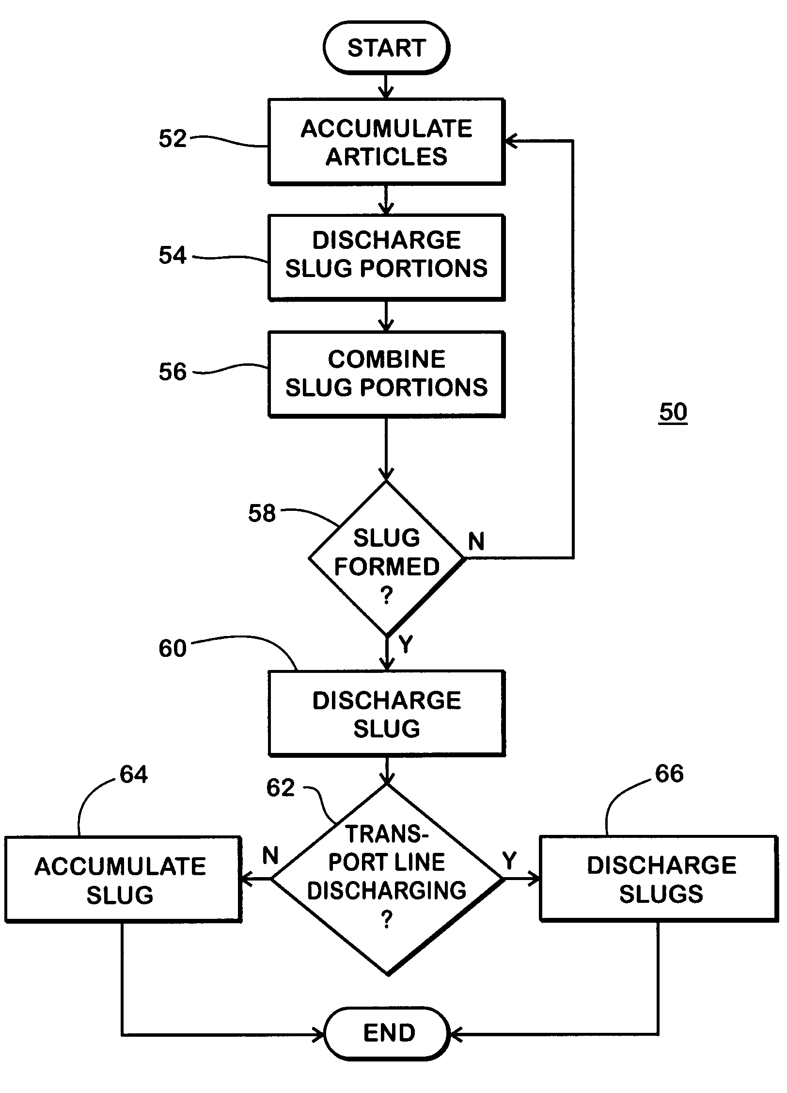
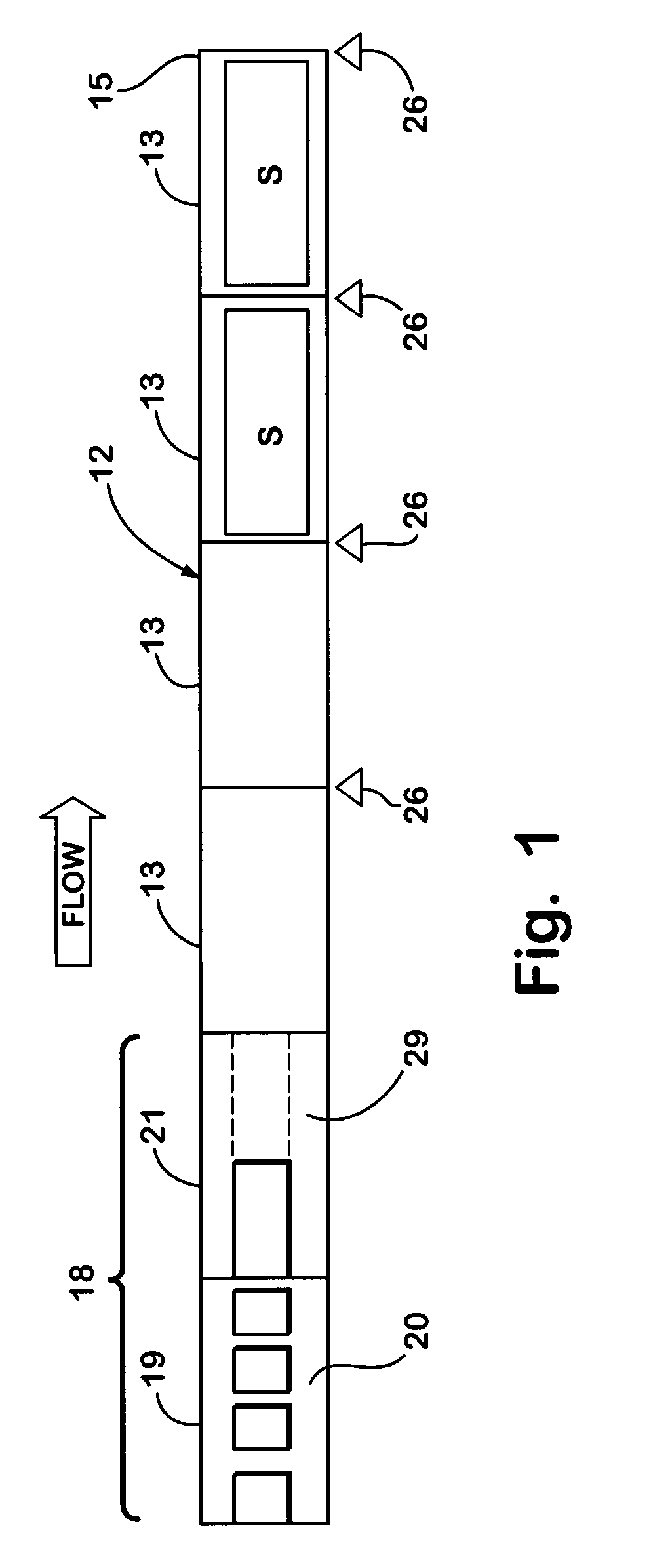
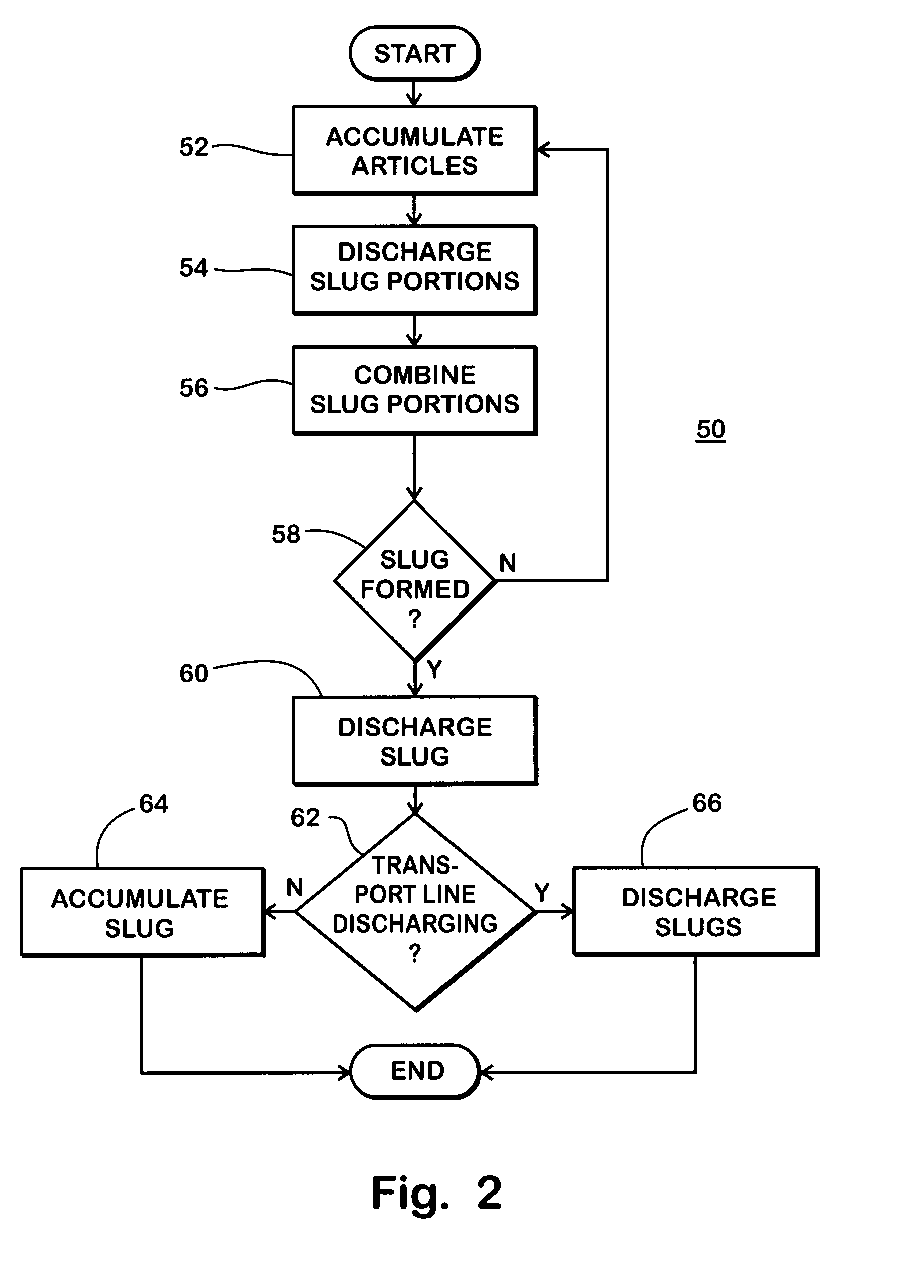
[0028]Referring now to the drawings and the illustrative embodiments depicted therein, an accumulation conveyor system 10 includes an accumulation assembly 18 for accumulating articles into slugs and a transport line 12 for transporting slugs and accumulating slugs as required (FIG. 1). A plurality of such accumulation systems may be combined and merged with a merge 14, the output of which is supplied to a downstream process 16 (FIG. 3). The downstream process may be a sortation process, a palletizer, an automatic storage and retrieval system, a shipping function, or the like. Accumulation assembly 18 may be made up of a slug forming section 19 and a slug combining section 21. The slug forming section accumulates articles into slug portions. The slug combining section accumulates slug portions into larger slugs. The slugs are discharged from the slug combining section and transported by transport conveyors 13 of the transport line to a terminal end 15 of the line. At the terminal en...


PUM


Abstract

An accumulation conveyor system and method of accumulating articles includes providing an accumulation assembly that is adapted to accumulating a plurality of articles into a slug of articles. Slugs of articles are discharged to a transport line which transports the slugs and accumulates the slugs as required. The accumulation assembly is made up of a slug forming section which forms slug portions and discharges slug portions into slugs. The accumulation assembly accumulates articles in zones and reduces gaps between articles in sequence from upstream gaps to downstream gaps.

Description

CROSS REFERENCE TO RELATED APPLICATIONS[0001]This application claims priority from U.S. provisional patent application Ser. No. 60 / 412,396, filed on Sep. 20, 2002, the disclosure of which is hereby incorporated herein by reference in its entirety.BACKGROUND OF INVENTION[0002]The present invention pertains to an accumulation technique and a conveyor system utilizing the accumulation technique. The invention may be applied to an individual accumulation conveyor line or to a conveyor system made up of a plurality of accumulation conveyor lines having outputs merged at a merge assembly.[0003]It is known to provide accumulation capability in conveyor systems in order to accommodate uneven throughput of articles in the system. For example, a conveyor system may receive articles on conveyor lines fed from loading doors in which trucks or other containers are discharged of articles at the loading doors. Some loading doors may be receiving articles, while others are not. Likewise, the convey...

Claims


Application Information

Patent Timeline
Patent Type & Authority Patents(United States)
IPC IPC(8): B65G13/06B65G43/00B65G43/10B65G47/26B65G47/31
CPCB65G47/261B65G43/10
Inventor HAAN, TED W.PELAK, WYNN M.
Owner DEMATIC
Why Eureka
Try Eureka