Mounting assembly

a technology of mounting assembly and mounting plate, which is applied in the direction of machine supports, building scaffolds, domestic objects, etc., can solve the problems of boating and instrument production, and the instruments are subject to even greater forces, so as to achieve the effect of easing engagemen

Inactive Publication Date: 2006-06-20
NAVICO HLDG
View PDF24 Cites 11 Cited by
  • Summary
  • Abstract
  • Description
  • Claims
  • Application Information

AI Technical Summary

Benefits of technology

[0006]Importantly, the mounting assemblies of the present invention include a first mount for connecting to a desired device and a second mount for connecting to a mounting object. The first and second mounts form a quick release mechanism to thereby mount the device of interest to the mounting object. The quick release mechanism allows the device mounted thereto to be rotated relative to the mounting object. This, in turn, allows the user to select a rotational position for the device. The quick release device may also include a lead-in feature that aids the user in connecting the first and second mounts together. Further, the quick release mechanism may include interlocking teeth that promote stability of the device when subjected to external forces. These and other features of the present invention are discussed further below.
[0008]According to one aspect of the invention, the cooperating detent members comprise at least one tooth that engages a detent in order to rotationally secure the first mount to the second mount. Either the teeth or the detents may be disposed on either the receptacle or the connector, and in one embodiment the teeth are disposed on the first mount while the detents are disposed on the receptacle of the second mount. The tooth may be disposed outwardly from the side of the resilient member, and thus the detents receive the tooth for secure engagement. In embodiment, the tooth may have a draft angle measured orthogonal to the first side. The detent has a corresponding draft angle to mate flush with the tooth. The draft angle permits the teeth to disengage from the second cooperating detent members upon sufficient lateral force.
[0010]Another aspect of the invention eases engagement of the at least one first cooperating detent members by depressing the resilient member inwardly prior to engaging the second cooperating detent members. A lead-in surface is disposed on the second mount and is beveled inwardly toward said receptacle. Therefore, a user may mount the connector into the receptacle by pressing the resilient member against the lead-in surface such that the resilient member is gradually depressed to the point of engagement of the cooperating detent members.

Problems solved by technology

The importance of securely mounting instruments is particularly apparent for fast-moving vehicles, which typically subject the instruments to even greater forces.
On boats, in particular, the instruments must withstand substantial forces acting on the instrument and the instrument panel resulting from choppy or rough water conditions.
Furthermore, forces resulting from acceleration and deceleration of the boat may also produce substantial forces on the instrument.

Method used


Image

  • Mounting assembly
  • Mounting assembly
  • Mounting assembly

Examples


Embodiment Construction

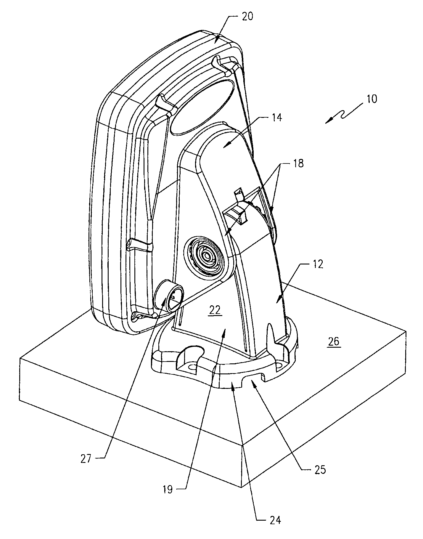
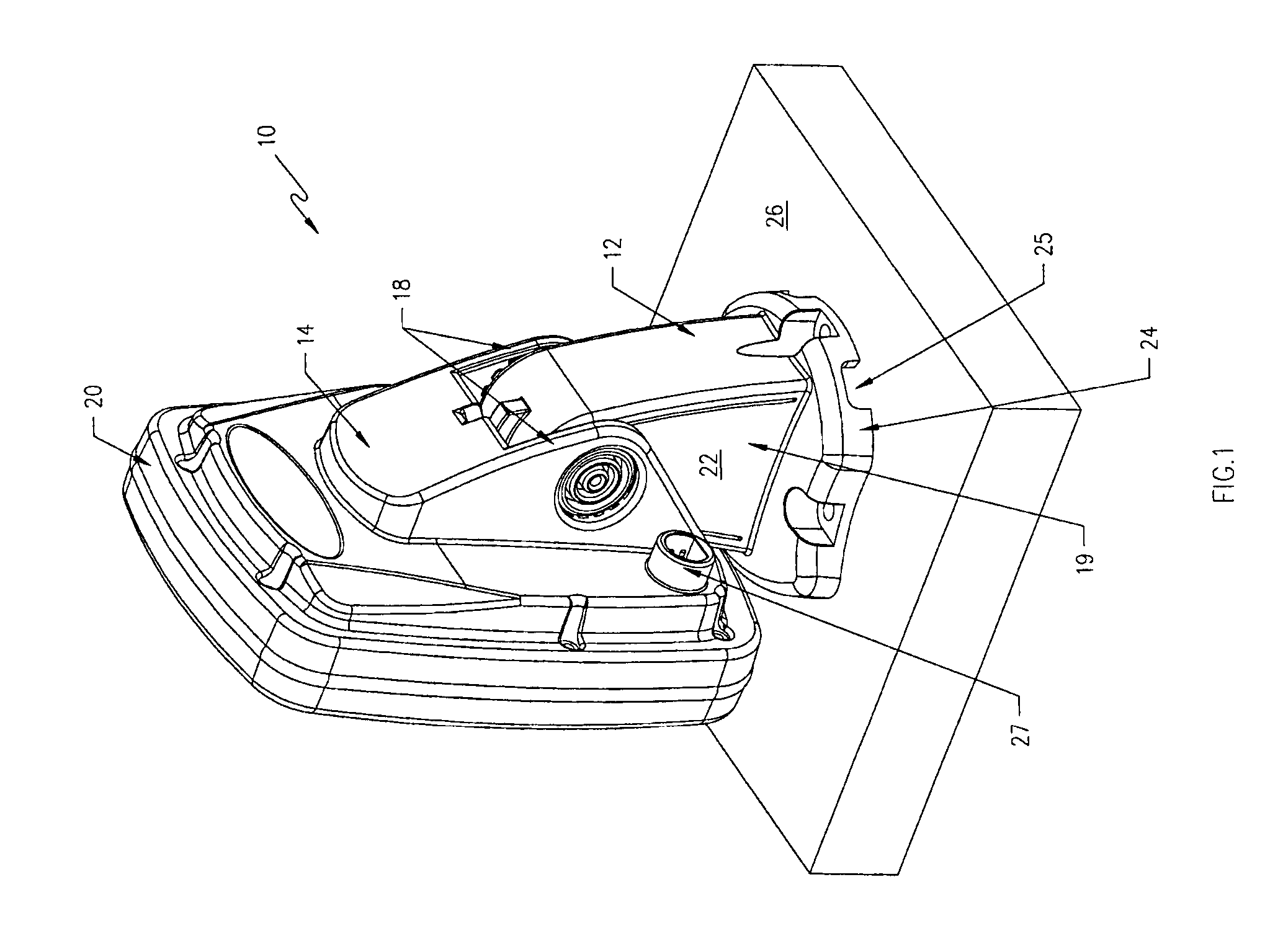
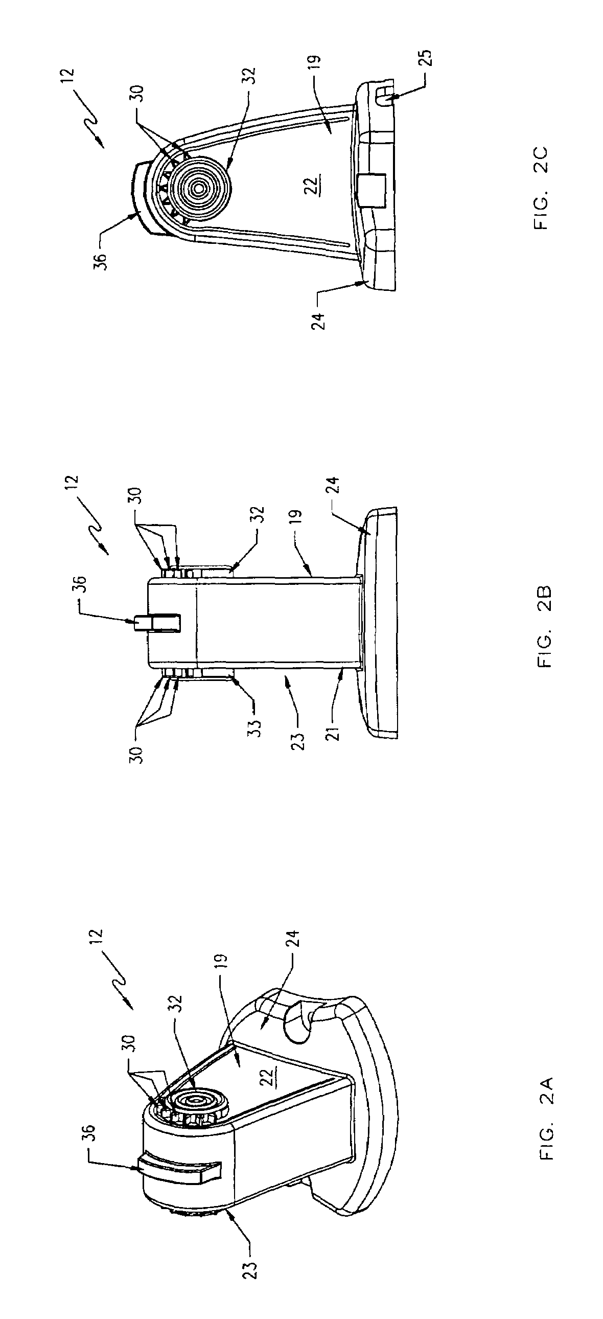
[0022]The present inventions now will be described more fully hereinafter with reference to the accompanying drawings, in which some, but not all embodiments of the inventions are shown. Indeed, these inventions may be embodied in many different forms and should not be construed as limited to the embodiments set forth herein; rather, these embodiments are provided so that this disclosure will satisfy applicable legal requirements. Like numbers refer to like elements throughout.

[0023]As an initial point, in the below description, the mounting assembly of the present invention is illustrated and discussed in the context of mounting electronics and similar devices to a dashboard or other mounting panel. It must be understood, however, that the mounting assembly has many general uses and that the description of the mounting assembly in an electronic mounting environment is only one use of the system. The embodiments described below are provided to promote a clear understanding of the in...


PUM


Abstract

A mounting assembly includes first and second mounts that connect two objects, such as an electronic instrument housing and a surface. The first mount engages the second mount at a receptacle by way of cooperating detent members. One mount includes a resilient member, upon which cooperating detent members are disposed. The resilient member provides a bias to cause secure engagement of the cooperating detent members. Other features of the mounting assembly include rotational engagement between first and second cooperating detent members such that the angle of the first mount may be adjusted with respect to the angle of the second mount. Also, lead-ins may be included on the second mount so that the resilient members on the first mount may be depressed to ensure proper engagement of the cooperating detent members.

Description

FIELD OF THE INVENTION[0001]The invention relates to mounting assemblies, and more particularly, to mounting assemblies having cooperating detent members for engaging a first mount to a second mount.BACKGROUND OF THE INVENTION[0002]Electronic instruments mounted on the dashboards or other panels of vehicles, such as boats, must be securely mounted to withstand the harsh conditions to which they may be subjected. The importance of securely mounting instruments is particularly apparent for fast-moving vehicles, which typically subject the instruments to even greater forces. On boats, in particular, the instruments must withstand substantial forces acting on the instrument and the instrument panel resulting from choppy or rough water conditions. Furthermore, forces resulting from acceleration and deceleration of the boat may also produce substantial forces on the instrument.[0003]Accordingly, it is necessary to securely mount the instruments to withstand these varying and harsh conditi...

Claims


Application Information

Patent Timeline
Patent Type & Authority Patents(United States)
IPC IPC(8): E04G3/00A47F5/12B60R11/00B60R11/02B63B29/06F16M11/10
CPCB60R11/02F16M11/041F16M11/10F16M13/00B60R11/0235B60R2011/0085F16M2200/024B63B29/06
Inventor JOPLING, KENTON
Owner NAVICO HLDG
Why Eureka
Try Eureka