
Systems and devices for cerebral aneurysm repair

a technology for cerebral aneurysms and systems, applied in the field of cerebral aneurysm repair systems and devices, can solve the problems of sub-arachnoid hemorrhage patients, risk of initiating an ischemic event during balloon remodeling, and flow arrest, so as to promote device stability, promote device stability, and increase the adhesion of the device

Active Publication Date: 2017-02-14
BLOCKADE MEDICAL
View PDF35 Cites 1 Cited by
  • Summary
  • Abstract
  • Description
  • Claims
  • Application Information

AI Technical Summary

Benefits of technology

[0013]Consequently, the inventor contemplates methods of forming an embolization device that includes a step of providing an embolization device having a body portion with a surface. In another step, the surface is treated such that the surface is electropositive under physiological conditions when the device is implanted into an artery, an aneurysm or vesicle, wherein the surface is sufficiently electropositive such that the surface ionically binds a physiologic component in an amount effective to promote stability in the artery, in the aneurysm or vesicle.
[0015]According to embodiments, there is provided An embolization device, comprising a body portion having a surface, wherein the body portion is configured to have a radiopaque and electropositive surface under physiological conditions when the device is implanted into an artery, aneurysm or vesicle; and, wherein the surface is sufficiently visualized and electropositive such that the surface ionically binds a blood component in an amount effective to promote stability of device in the artery, aneurysm or vesicle, or to bind to a tissue component in an amount effective to increase adhesion of the device as compared to a device without electropositive surface.
[0016]According to embodiments, there is provided a method of forming an embolization device, comprising providing an embolization device having a body portion with a surface; treating the surface such that the surface is electropositive under physiological conditions when the device is implanted into an aneurysm or vesicle; and, wherein the surface is sufficiently electropositive such that the surface ionically binds a blood component in an amount effective to promote stability of devices in the artery, aneurysm or vesicle, or to bind to a tissue component in an amount effective to increase adhesion of the device as compared to a device without electropositive surface.

Problems solved by technology

However, patients with sub-arachnoid hemorrhage (SAH) are typically not candidates for stents due the prophylactic drug regimen to mitigate the thrombo-embolic complications.
However, during this technique, flow arrest is performed while the balloon is inflated.
There is a risk of initiating an ischemic event during balloon remodeling and / or a thrombo-embolic event during flow arrest.
Although these markers verify the placement and / or deployment of the devices within the artery in relation to the abnormality to be repaired, verification of the complete opening or apposition to the artery wall or aneurysm neck cannot be verified unless a contract enhanced CT is performed.
In most cases, complete embolization of the aneurysm with currently known devices will typically require at least several coils and devices, and / or are incomplete treatment of the aneurysm because the wall apposition and neck reconstruction of the aneurysm neck is insufficient and the coils previously placed have moved, or the visualization of the neck reconstruction was non-existent and the physician was unable to verify the proper placement of embolization devices at the aneurysm neck.
The difficulties of stabilizing known devices within an aneurysm or vesicle are multiplied when aneurysm necks are wide, or the inflow zone of the aneurysm is in a high shear area (e.g., at a curve or bifurcation).
Further, it is not uncommon that sufficient amounts of devices cannot be placed into the aneurysm without losing microcatheter access due to aneurysm, aneurysm neck or vesicle morphology.
Additionally, currently known devices can often not readily be stabilized within the aneurysm due to their visibility, softness and inertness.

Method used


Image

  • Systems and devices for cerebral aneurysm repair
  • Systems and devices for cerebral aneurysm repair
  • Systems and devices for cerebral aneurysm repair

Examples


Embodiment Construction

[0032]The inventor has discovered that embolization devices with improved implantation characteristics, and especially with improved radiopacity, retention of implants and / or biocompatibility, can be prepared by inclusion of a radiopaque, electropositive surface on the device, wherein the surface is sufficiently electropositive such that the surface ionically binds one or more physiologic components in an amount effective to promote stability of physiologic components in the artery, aneurysm or vesicle, or to bind to a tissue component in an amount effective to increase adhesion of the device as compared to a corresponding device without radiopaque, electropositive surface. While not limiting to the inventive subject matter, it is especially preferred that the radiopaque, electropositive surface is provided by a radiopaque, electropositive metal that is coupled to the body of the embolization device.

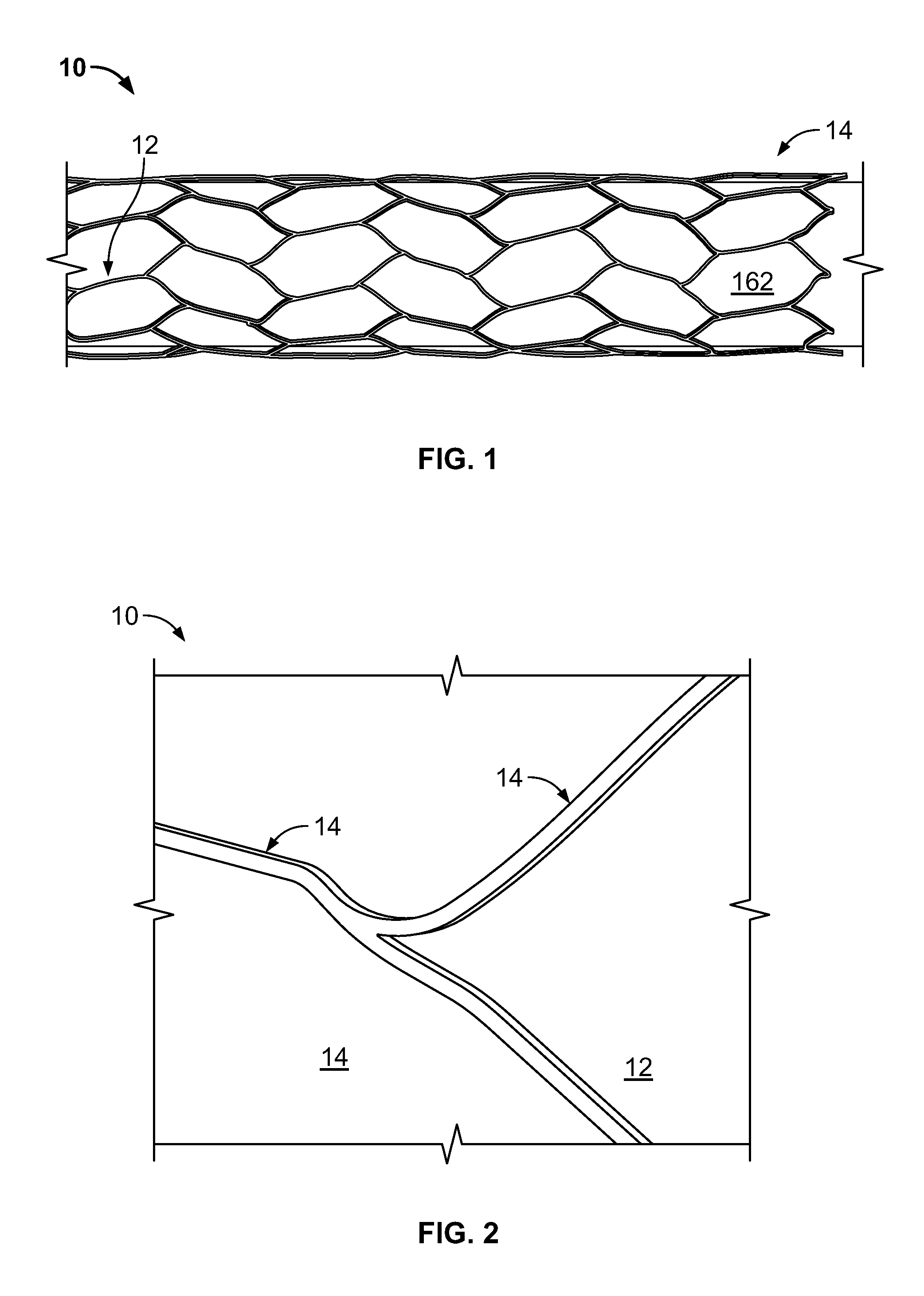
[0033]FIG. 1 and FIG. 2 provide exemplary illustrations of the inventive subject mat...


PUM

PropertyMeasurementUnit
currentaaaaaaaaaa
currentaaaaaaaaaa
voltageaaaaaaaaaa

Abstract

An embolization device for treating ischemic stroke is disclosed, having a surface, wherein the body portion is configured to have a radiopaque and electropositive surface under physiological conditions when the device is emplaced, which ionically binds a blood component in an amount effective to promote stability of device in situ to bind to a tissue component in an amount effective to increase adhesion of the device as compared to a device without an electropositive surface. Embolic coils being so delivered are electrolytically detachable in under 10 seconds, according to the disclosed vascular implant systems.

Description

CROSS-REFERENCE TO RELATED APPLICATION[0001]This application claims the full Paris Convention priority of, and expressly incorporates by this reference U.S. provisional patent application 61 / 811,055, filed on Apr. 11, 2013, U.S. provisional patent application No. 61 / 888,240, filed Oct. 8, 2013, U.S. provisional patent application No. 61 / 917,854, filed Dec. 18, 2013, International Application No. PCT / US2005 / 020667, filed Jun. 13, 2005, International Application No. PCT / US2014 / 031666, filed Mar. 25, 2014, and U.S. Pat. No. 8,002,822, issued Aug. 23, 2011, the contents of which are incorporated by this reference, as if fully set forth herein in their entirety.FIELD OF INVENTIONS[0002]The field of the invention is compositions, devices, and methods of devices to repair cerebral aneurysms, especially as it relates to cerebral arterial repair of aneurysms, embolization of vascular abnormalities, most particularly neurovascular treatment of cerebral aneurysms.BACKGROUND[0003]The background...

Claims


Application Information

Patent Timeline
Patent Type & Authority Patents(United States)
IPC IPC(8): A61B17/12A61L31/08A61L31/02A61L31/18A61B17/00
CPCA61B17/12113A61B17/12109A61B17/12145A61B17/12154A61L31/022A61L31/088A61L31/18A61B2017/00893A61B2017/1209A61B2017/12063A61B2090/3966A61L2430/36
Inventor TAKAHASHI, RANDALLFERRERA, DAVID
Owner BLOCKADE MEDICAL
Learn More