Process for creating a durable EMI/RFI shield between two or more structural surfaces and shield formed therefrom

a technology of emi/rfi shield and structural surface, which is applied in the direction of magnetic/electric field screening, electric devices, etc., can solve the problems of limiting the shielding capability of the shelter, limiting the overall capability and effectiveness of the shield, etc., and achieves the effect of convenient transportation and maintaining performan

Inactive Publication Date: 2006-06-20
TYSON KENNETH E +1
View PDF7 Cites 46 Cited by
  • Summary
  • Abstract
  • Description
  • Claims
  • Application Information

AI Technical Summary

Benefits of technology

[0030]Still another object of the invention is to provide a shelter that is effectively resistant to the penetration of electromagnetic interference that is has a shield that is resistant to fatigue, chipping and cracking.
[0031]A further object of the invention is to provide a shelter that is readily transportable and resistant to a wide range of electromagnetic interferences.
[0032]According to another object of the invention, an EMI / RFI shield is provided that is durable and resistant to shock, vibrations and severe weather conditions and still maintain performance and has a corrosion resistant outer coating.

Problems solved by technology

It can been seen that seams and joints in an EMI / RFI shelter, for example, may limit the shielding capability of the shelter when exposed to a radiated electromagnetic field.
Seams may allow the electromagnetic interference fields to bypass or be transmitted through the shield thereby limiting the overall capability and effectiveness of the shield.

Method used


Image

  • Process for creating a durable EMI/RFI shield between two or more structural surfaces and shield formed therefrom
  • Process for creating a durable EMI/RFI shield between two or more structural surfaces and shield formed therefrom
  • Process for creating a durable EMI/RFI shield between two or more structural surfaces and shield formed therefrom

Examples


example 1

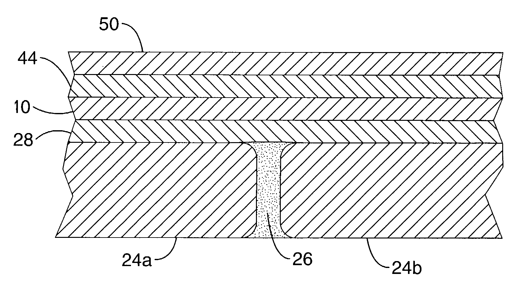
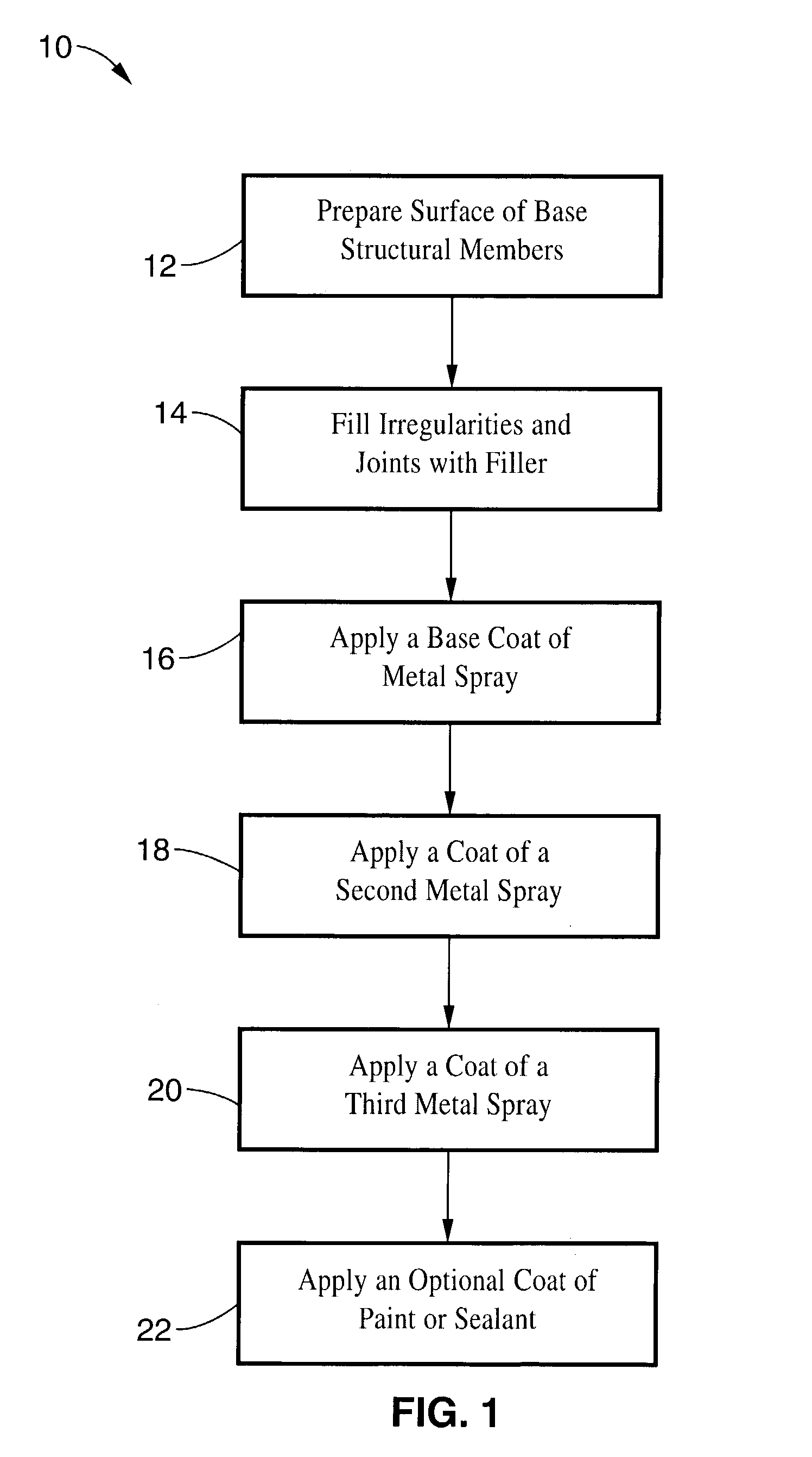
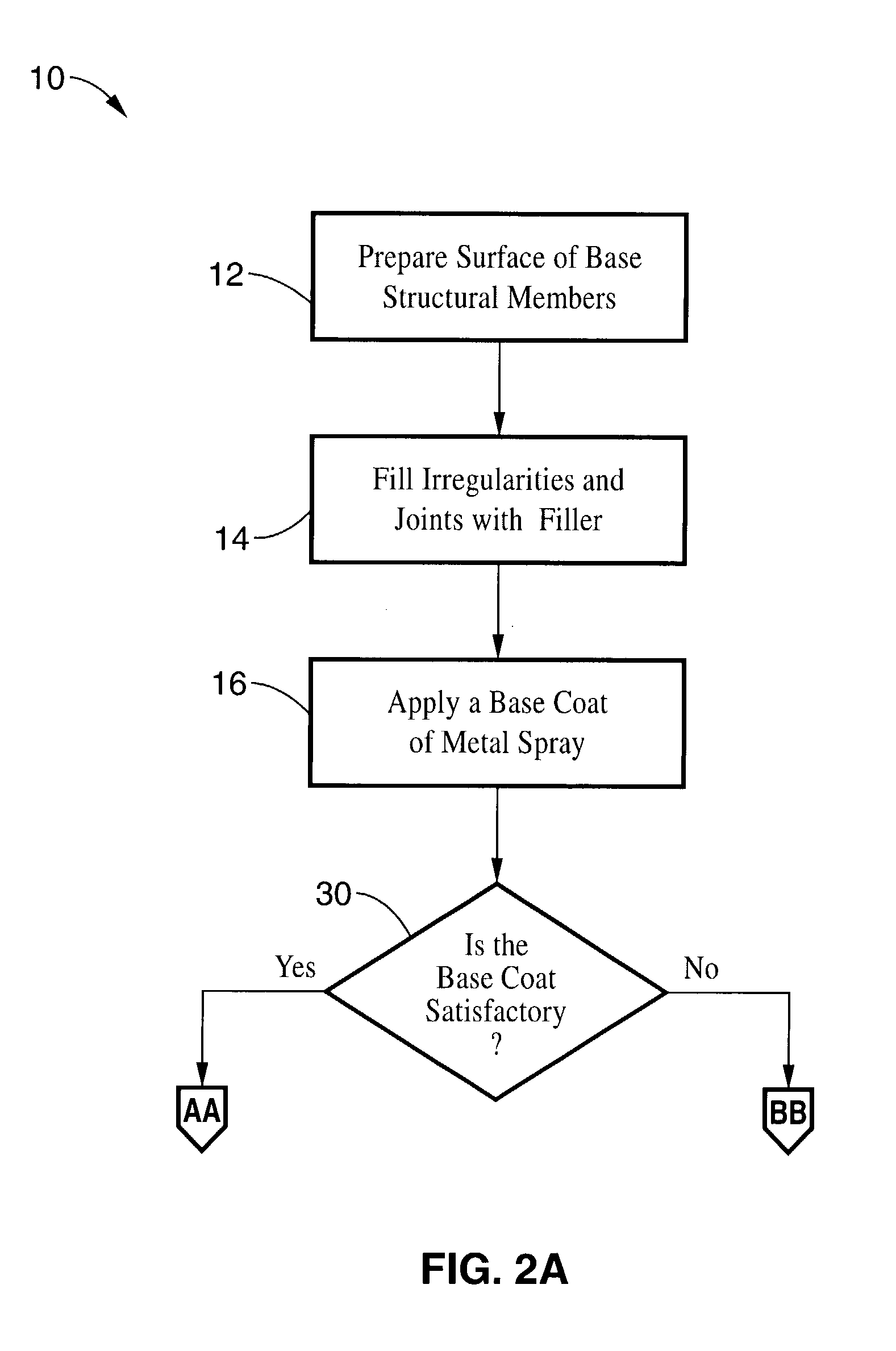
[0087]A lightweight multipurpose shelter, configured for placement on the back or frame of a truck, was produced using aluminum skin, hot bonded panels with a welded aluminum extrusion framework. The exterior dimensions of the shelter were 84 inches in width by 102 inches in length by 67 inches in height.

[0088]Extruded aluminum frame members were sized, cut and then welded together to create panel frame weldments. A honeycomb core material was placed into the frame weldments and properly dimensioned panels of aluminum sheets were sized, cut and hot bonded to both sides of the frame weldment / honeycomb core structure using film adhesive and core splice adhesive materials. The surfaces of the top, bottom, sides, front and back were prepared by removing all adhesive and core splice residue, as well as cleaning off the corrosion inhibiting primer from extruded frame members and the interior skin surface of the panel approximately ½″ away from the bond line between the frame member and th...


PUM

PropertyMeasurementUnit
thicknessaaaaaaaaaa
thicknessaaaaaaaaaa
thicknessaaaaaaaaaa

Abstract

A method for producing a durable electromagnetic and radio frequency interference shield between two or more structural members of a wall or enclosure and a shielded shelter produced using the method. In one embodiment, joints between structural members are preferably filled with an electrically conductive filler. A base coat of a metal spray that adheres well to the filler and structural member is then applied. At least one layer of a metal spray with magnetic field attenuation properties such as steel, and at least one layer of a metal spray that has plane wave attenuation properties such as tin are applied to the base coat. Optionally, a coat of protective or conductive paint is then applied to the top surface of the metal spray layers. An enclosure with shielded joints according to the present invention has superior shielding capability and durability over the art.

Description

CROSS-REFERENCE TO RELATED APPLICATIONS[0001]This application claims priority from U.S. provisional application Ser. No. 60 / 355,130 filed on Feb. 8, 2002, incorporated herein by reference. STATEMENT REGARDING FEDERALLY SPONSORED RESEARCH OR DEVELOPMENT[0002]Not Applicable REFERENCE TO A COMPUTER PROGRAM APPENDIX[0003]Not ApplicableBACKGROUND OF THE INVENTION[0004]1. Field of the Invention[0005]This invention pertains generally to EMI / RFI penetration resistant structural materials, and more particularly to a process for creating a durable EMI / RFI shield between two or more adjacent metal surfaces.[0006]2. Description of the Background Art[0007]Many household, industrial, commercial and military electronic devices are susceptible to interference by electromagnetic and radio frequency radiation sources in their surrounding environment. A radio frequency circuit, for example, often requires shielding to prevent electromagnetic energy generated by the circuit from interfering with the c...

Claims


Application Information

Patent Timeline
Patent Type & Authority Patents(United States)
IPC IPC(8): H05K9/00
CPCH05K9/0088
Inventor TYSON, KENNETH E.TYSON, DEBORAH S.MARZAN, THEODOREWALKER, RONALD B.
Owner TYSON KENNETH E
Why Eureka
Try Eureka