

Actuator film material, actuator film and actuator using the same
a technology of actuator film and actuator film, which is applied in the direction of mechanical equipment, generators/motors, machines/engines, etc., can solve the problems of severe deterioration of the actuator film, low response speed, etc., and achieve low operating noise, safe and stable use, and light weight
- Summary
- Abstract
- Description
- Claims
- Application Information
AI Technical Summary
Benefits of technology
Problems solved by technology
Method used
Image

Examples
example 1
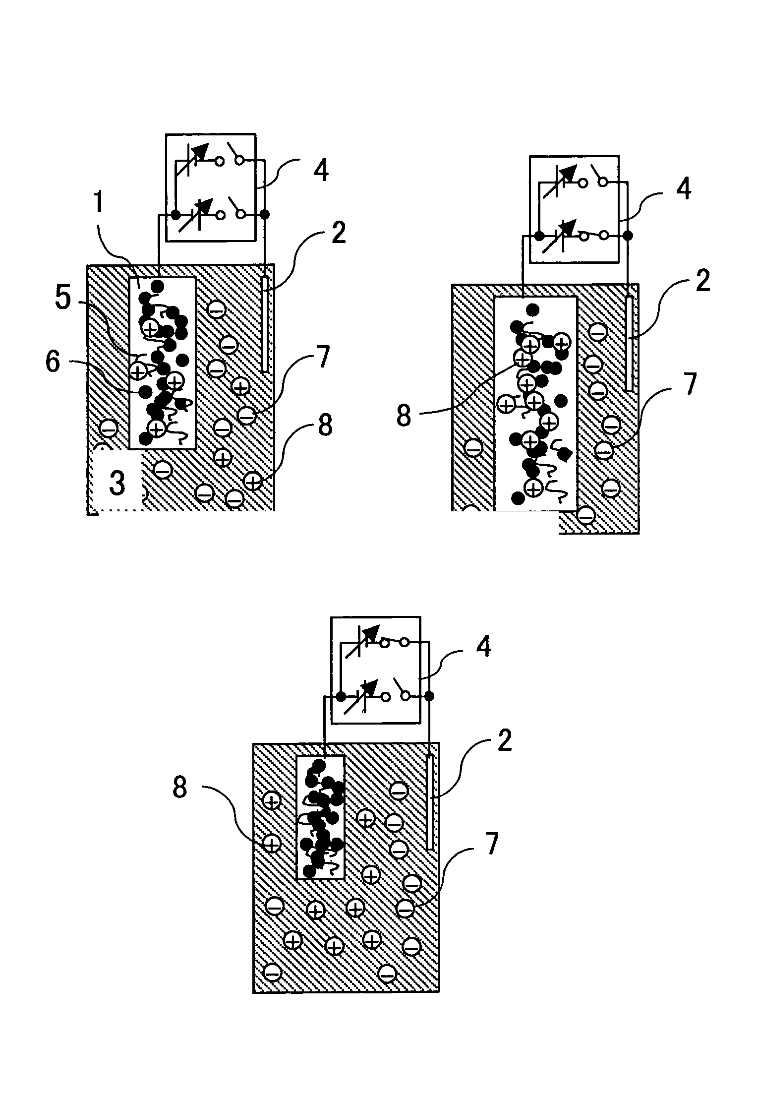
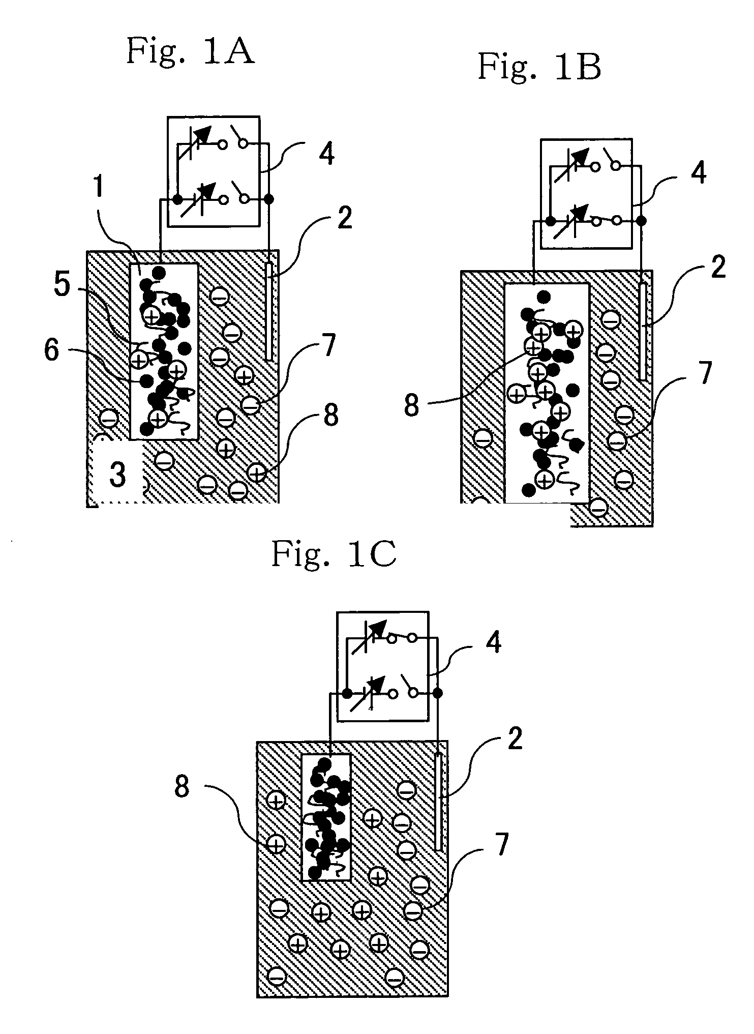
[0048]In Example 1, the concept of the essential motion of the actuator of the present invention and its manufacturing process will be described. First, the outline of the essential motion will be described referring to FIG. 1A to FIG. 1C. FIG. 1A to FIG. 1C are each a schematic view for explaining a constitution necessary for operating the actuator of the present invention, and expansion and contraction motion of an actuator film, which will generate a driving force of the actuator, when a voltage is applied to the actuator film.
[0049]The actuator of Example 1 is composed of an actuator film 1, a counter electrode disposed opposite thereto, an electrolyte solution 3 in which the actuator film 1 and counter electrode 2 are to be dipped, and a voltage supply 4 for applying a voltage to the actuator film 1 and counter electrode 2. To the voltage supply 4, a circuit having a power supply and a switch connected in series is connected in parallel and the power supply of the circuit conne...
example 2
[0073]In Example 2, various modes of the actuator film 1 described in Example 1 will be explained referring to FIG. 4 to FIG. 12D.
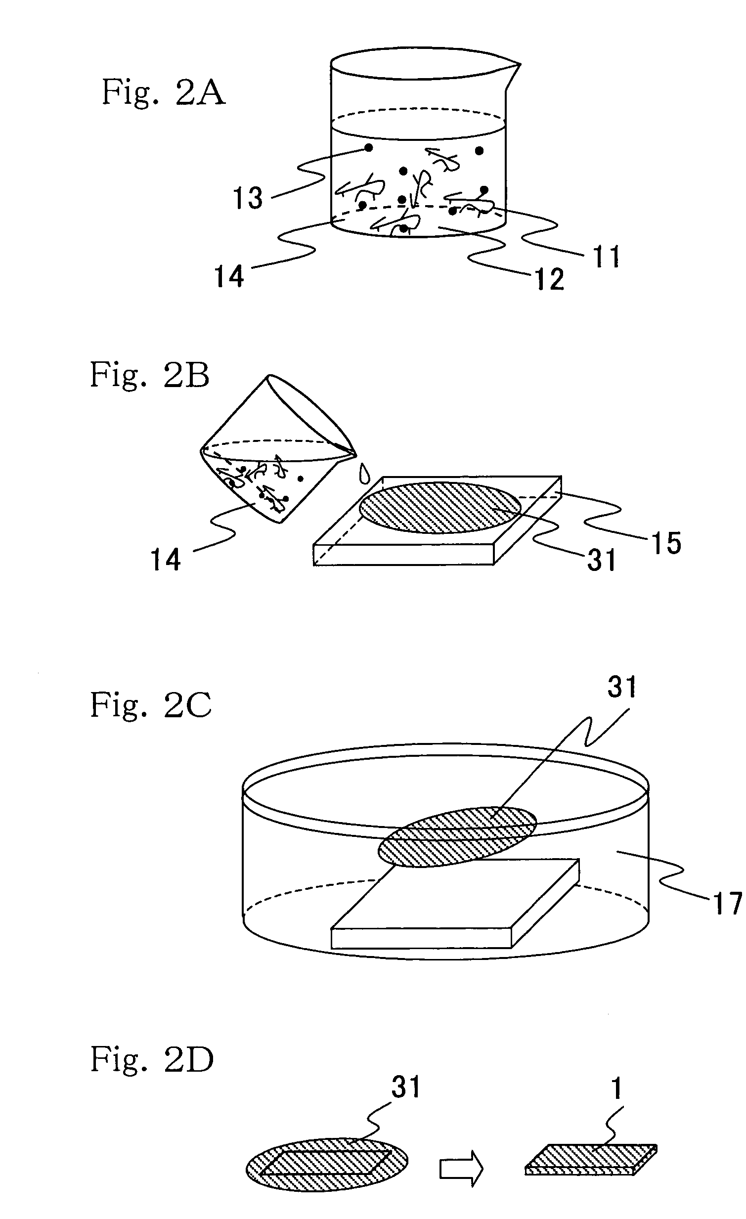
[0074]FIG. 4 is a perspective view illustrating the simplest structure of the actuator film 1 described in Example 1. As illustrated in the diagram, large expansion / contraction motion is caused in the direction of an x axis on a xyz rectangular coordinate system. This actuator film 1 is characterized by its constitution having a mixed film 31 of an ion conductive polymer having a capacity of capturing negative electrolyte ions or positive electrolyte ions ionized in an electrolyte solution and conductive fine particles, and a terminal electrode 32 for connecting it the actuator film to a power supply. It has thus a simple structure and therefore can be manufactured easily only by attaching the terminal electrode 32 to the actuator film obtained in FIG. 2D. In FIG. 4, the film is connected to the power supply at only the terminal electrode32 existing at on...
example 3
[0104]FIG. 11A and FIG. 11B are each a schematic diagram illustrating an essential structure and operation principle of an actuator film for converting expansion / contraction motion of the actuator film to bending motion having a large displacement level and obtaining as expansion / contraction motion in a uniaxial direction. FIG. 11A illustrates the motion before application of a voltage, while FIG. 11B illustrates the motion when a voltage is applied. The actuator film 1 is composed of a unit actuator film 101, a resin thin-film 102, a conductor 103 covering both surfaces of the resin thin-film 102 and a terminal electrode 32 for connection with a power supply. As illustrated in the drawing, large expansion / contraction motion is produced in the direction of an x axis on a xyz rectangular coordinate system. The resin thin-film 102 is a rectangular parallelepiped longer in the x direction and thin in the z direction.
[0105]This actuator film 1 has a plurality of unit actuator films 101 ...
PUM
 Abstract
Description
Claims
Application Information