
Fuel cell system and control method

a fuel cell and control apparatus technology, applied in the direction of electric variable regulation, process and machine control, instruments, etc., can solve problems such as fuel cell deterioration

Active Publication Date: 2006-06-20
HITACHI LTD +1
View PDF5 Cites 160 Cited by
  • Summary
  • Abstract
  • Description
  • Claims
  • Application Information

AI Technical Summary

Benefits of technology

[0017]a limiter for detecting the fuel cell voltage and reducing the limit value of the power instruction value in accordance with the fuel cell voltage drop and the power instruction value being set as the limit value when the fuel cell voltage falls down to the first threshold value.

Problems solved by technology

Moreover, since the load setting value is only reduced in accordance with the amount of voltage reduction, there is a possibility of deteriorating the fuel cell when the fuel cell has taken load just before the protection stop level thereof.

Method used


Image

  • Fuel cell system and control method
  • Fuel cell system and control method
  • Fuel cell system and control method

Examples


embodiment 2

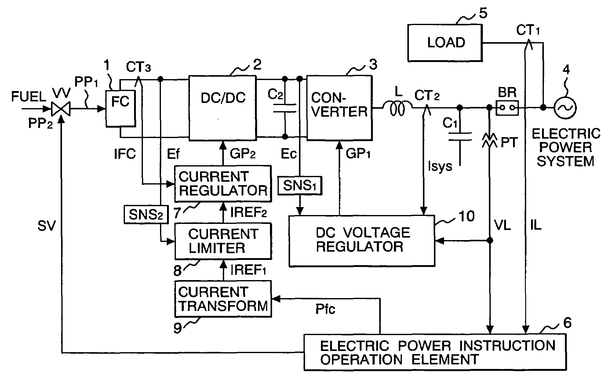
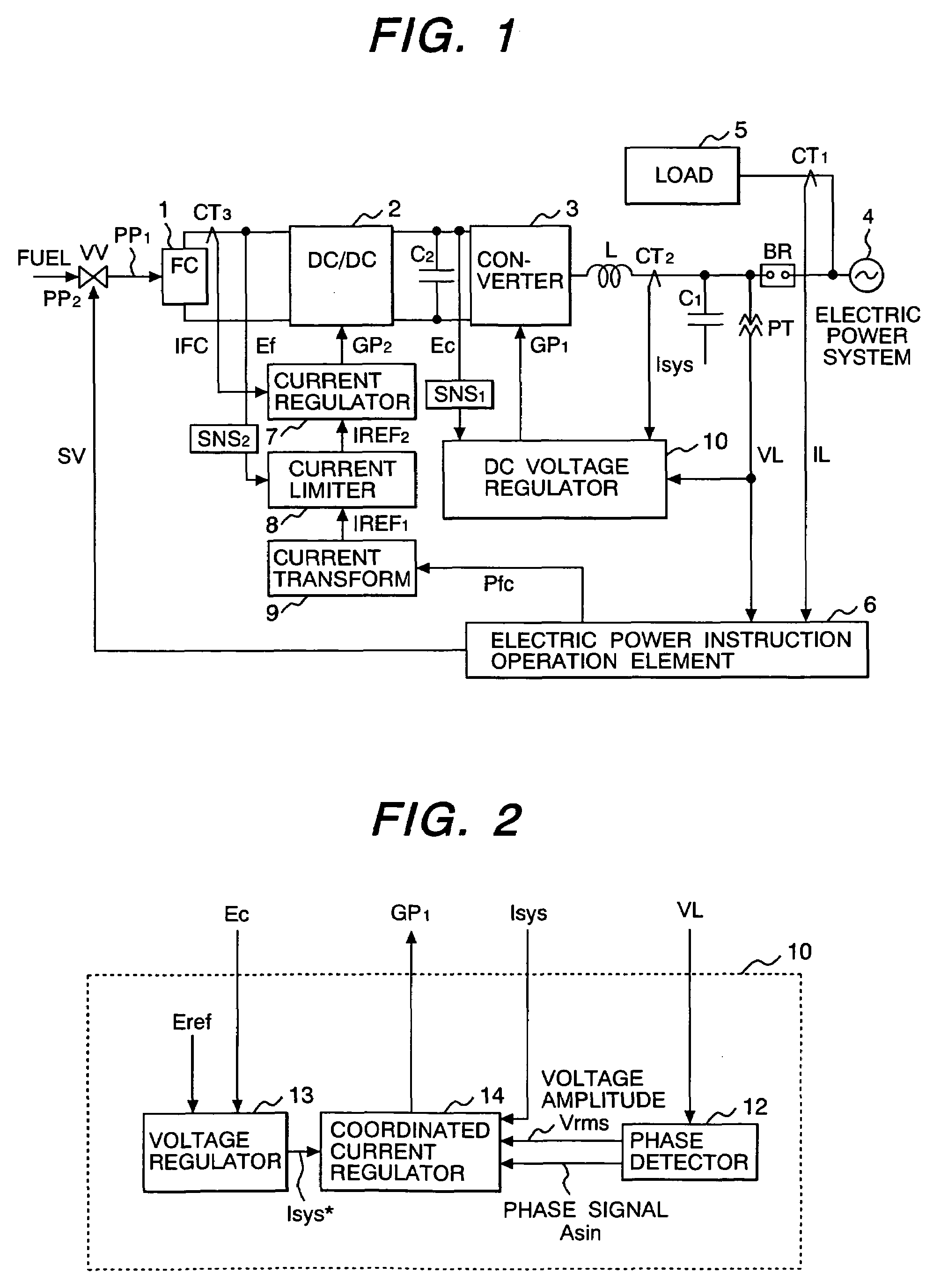
[0057]Next, other embodiment of the operation of the invention will be explained. FIG. 8 is a block diagram showing the system configuration of the operation control apparatus of the fuel cell by an The diagram shows a voltage type power converter with the function to transform the AC electric power of single-phase AC electric power or single phase AC into DC electric power. The same reference signs as FIG. 1 show the same parts of the FIG. 1 and explanation is omitted.

first embodiment

[0058]FIG. 8 differs from the first embodiment in that the fuel cell(FC) 1 is connected to the DC side of the capacitor C2 of the converter 3 which transforms DC electric power into AC electric power. The detection value IL of the current detector CT1 installed in the input of load 5, and the detection value VL of a voltage detection means PT to detect the voltage of the electric power system 4 are inputted into the electric power instruction operation element 6. The electric power instruction operation element 6 outputs the opening signal SV of the valve VV for the fuel regulation supplies to the valve VV and calculates the electric power instruction value Pfc.

[0059]The electric power instruction value Pfc is inputted into the current converter 9 and multiplied by the gain transforming the electric power into the current, and outputs the output current setting value IREF1 of the fuel cell to the current limiter 8. The output current setting value of the fuel cell IREF1 and the fuel...


PUM


Abstract

A battery voltage Ef of a fuel cell 1 is detected, and a current instruction value which transformed an electric power instruction value Pfc of the fuel cell is reduced at falling-down of the voltage Ef. A current limiter 8 makes the current instruction value a limit value at the time of the falling-down of Ef, and reduces the limit value according to the fall of Ef. For example, current instruction value is restricted so as to begin to reduce battery current IFC at voltage drop alarm level (first threshold value), and become zero at voltage drop protection level (second threshold value).

Description

BACKGROUND OF THE INVENTION[0001]The present invention relates to an operation control apparatus for a fuel cell suitable to prevent it from deteriorating and method for controlling thereof.[0002]When the fuel cell characteristic is changed by deterioration or load is changed rapidly, the DC output of the fuel cell reduces below a set value transitionally, even if reaction gas is supplied and the fuel cell itself is normal.[0003]Japanese Laid-open Patent Publication 2000-21429 discloses that a load setting value is reduced in accordance with reduction of the fuel cell voltage to protect it by operation of a reverse converter, when the voltage of the fuel cell falls down.SUMMARY OF THE INVENTION[0004]In the above conventional reference, the load setting value is reduced according to the amount of voltage reduction of the fuel cell. For this reason, if the load setting value is fallen down by load change, the current outputted from the fuel cell will also be changed. Moreover, since t...

Claims


Application Information

Patent Timeline
IPC IPC(8): H02H7/122H02H7/00H01M8/04H02J3/38
CPCH01M8/04559H01M8/0491H02J3/387Y02E60/50H02J2001/004H02M2001/007H02J2300/30H02J3/381H02M1/007
Inventor ICHINOSE, MASAYATAKEDA, KENJIFUTAMI, MOTOOKOMACHIYA, MASAHIROKUBO, KENJI
Owner HITACHI LTD
Learn More