System and method for providing a write strobe signal to a receiving element before both an address and data signal

a technology of strobe signal and receiving element, applied in the field of electronic circuits, can solve the problems of inaccessible sfrs in the peripheral that is inaccessible during the shut down period, inability to provide free running clock, undesirable delay logic, etc., and achieve the effect of reducing the minimum insertion delay and high system speed

Inactive Publication Date: 2006-06-20
TEXAS INSTR INC
View PDF7 Cites 2 Cited by
  • Summary
  • Abstract
  • Description
  • Claims
  • Application Information

AI Technical Summary

Benefits of technology

[0009]In accordance with another aspect of the present invention, clock tree distribution techniques may be used to achieve significantly higher system speed. When balancing the clock network of the system, the clock leaf of the flip-flop or other circuit element that generates the SFR write strobe signal may be “advanced.” The clock leaf of the SFR write strobe signal generating circuit element (e.g., the flip-flop) may be “advanced” by connecting the circuit element directly to the clock root. In addition, the SFR write strobe signal distribution may be balanced as a separate clock tree with minimum insertion delay.

Problems solved by technology

A peripheral can be shut down by stopping the peripheral's clock, however, which causes the SFRs that reside in that peripheral to be inaccessible during the shut down period.
However, in many systems, such as in lower power applications, a free running clock is not provided due to the high power consumption of the free running clock.
However, these solutions require delay logic so that the SFR address and data buses remain valid while the SFR is reactivated.
The delay logic is undesirable as it adds complexity and slowness to the system.
Moreover, if the SFR access is in the critical path of a system, delaying the availability of the address and data may require slowing down the system clock frequency.

Method used


Image

  • System and method for providing a write strobe signal to a receiving element before both an address and data signal
  • System and method for providing a write strobe signal to a receiving element before both an address and data signal
  • System and method for providing a write strobe signal to a receiving element before both an address and data signal

Examples


Embodiment Construction

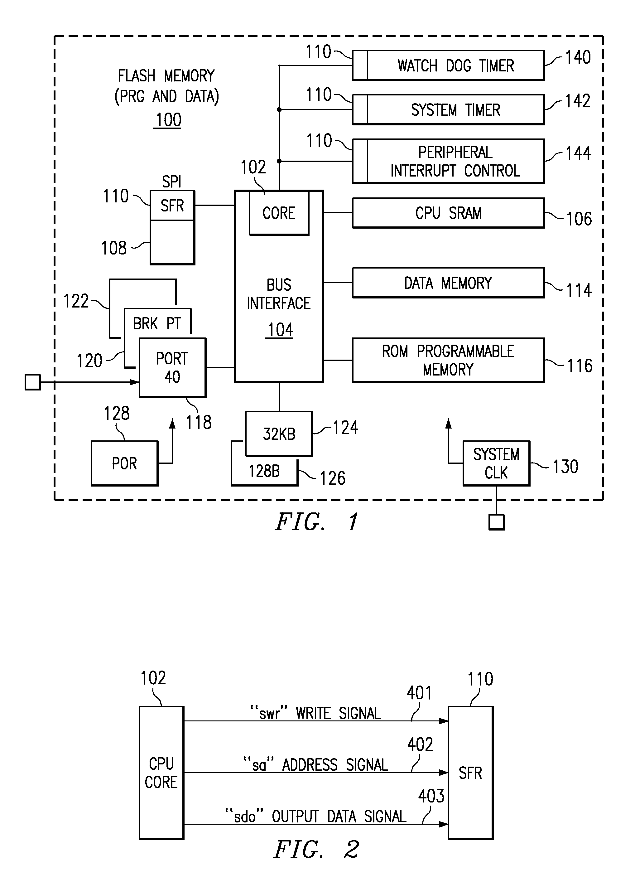
[0017]The present invention may be described in terms of various functional components and various processing steps. Such functional components may be realized by any number of hardware or structural components configured to perform the specified functions. For example, the present invention may employ various integrated components, e.g., buffers, storage devices, peripheral devices, memory components, and the like, comprised of various electrical devices, e.g., resistors, transistors, capacitors, diodes, logic elements, or other devices, whose values and characteristics may be suitably configured for various intended purposes. In addition, the present invention may be practiced in any data writing application. Such general applications are not described in detail herein. However for purposes of illustration only, exemplary embodiments of the present invention are described in connection with a microcontroller.

[0018]Further, while various components may be suitably coupled or connec...


PUM


Abstract

A method and apparatus is provided for that includes an improved special function register (SFR) access scheme by using a clock tree distribution process. In accordance with an exemplary embodiment, a conditional SFR write strobe signal may be used to trigger the SFR registers. A clock tree distribution process may be used to achieve significantly higher system speed. When balancing the clock network of the system, the clock leaf of the flip-flop or other circuit element that generates the SFR write strobe signal may be “advanced” by connecting the circuit element directly to the clock root. In addition, the SFR write strobe signal distribution may be balanced as a separate clock tree with minimum insertion delay.

Description

CROSS-REFERENCE TO RELATED APPLICATIONS[0001]This application claims priority to, and the benefit of, U.S. Provisional Patent Application Ser. No. 60 / 289,010, entitled “METHOD AND DEVICE FOR PROVIDING NON-INTERRUPT REGISTER ACCESS” and filed on May 4, 2001, which is hereby incorporated by reference in its entirety.TECHNICAL FIELD[0002]The present invention relates to electronic circuits.BACKGROUND INFORMATION[0003]The demand for higher performance, microcontroller-based products for use in communication and processing applications continues to increase rapidly. As a result, microcontroller-based product manufacturers are requiring the components and devices within these products to be continually improved to meet the design requirements of a myriad of emerging audio, video and imaging applications.[0004]These microcontroller-based products use various types of processors, for example, general purpose microprocessors for controlling the logic of various digital devices, such as clock...

Claims


Application Information

Patent Timeline
Patent Type & Authority Patents(United States)
IPC IPC(8): G06F1/04G06F13/00G06F1/10
CPCG06F1/10
Inventor CHEUNG, HUGOYUAN, LUCHIU, TERENCE
Owner TEXAS INSTR INC
Why Eureka
Try Eureka