Multi-array detector module structure for radiation imaging

a detector module and radiation imaging technology, applied in the field of radiation detection, can solve the problems of difficult technical implementation, limited improvement of the repetition frequency of the accelerator, and significant increase of the power consumption of the whole radiation imaging system, so as to reduce cross talk and reduce diffusion

Active Publication Date: 2007-07-26
NUCTECH CO LTD
View PDF7 Cites 5 Cited by
  • Summary
  • Abstract
  • Description
  • Claims
  • Application Information

AI Technical Summary

Benefits of technology

[0013] heavy metal sheets provided between respective detector arrays in respective rows of detector arrays, for reducing cross talk.
[0014] Preferably, heavy metal pla

Problems solved by technology

In practice, improvement of the repetition frequency of the accelerator is limited, because such improvement is difficult to be technically implemented.
Further, intensity of the radiation field of the whole radiation imaging system is caused to increase, so that it is difficult to implement desirable radiation protection, and power consumption of the whole radiation imaging system will be considerably increased.
Also, radiation field efficiency of exis

Method used


Image

  • Multi-array detector module structure for radiation imaging
  • Multi-array detector module structure for radiation imaging
  • Multi-array detector module structure for radiation imaging

Examples


Embodiment Construction

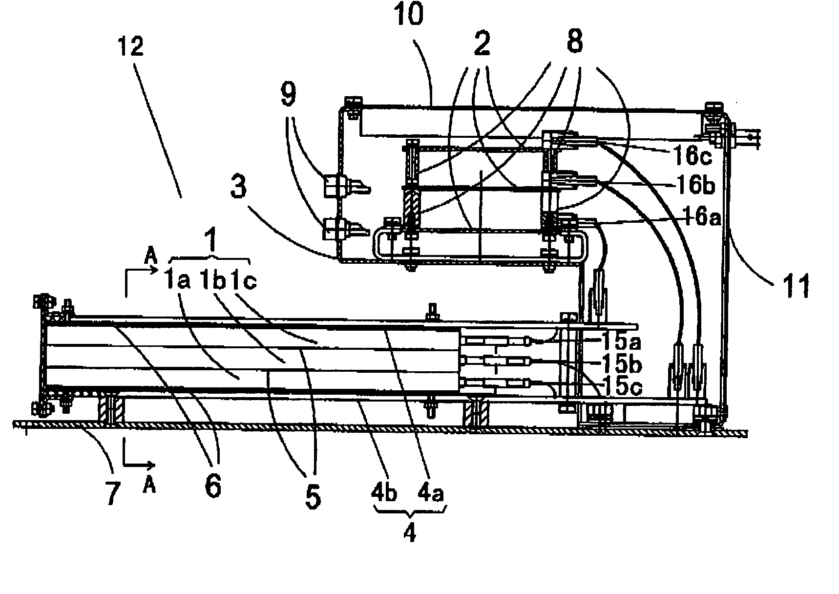
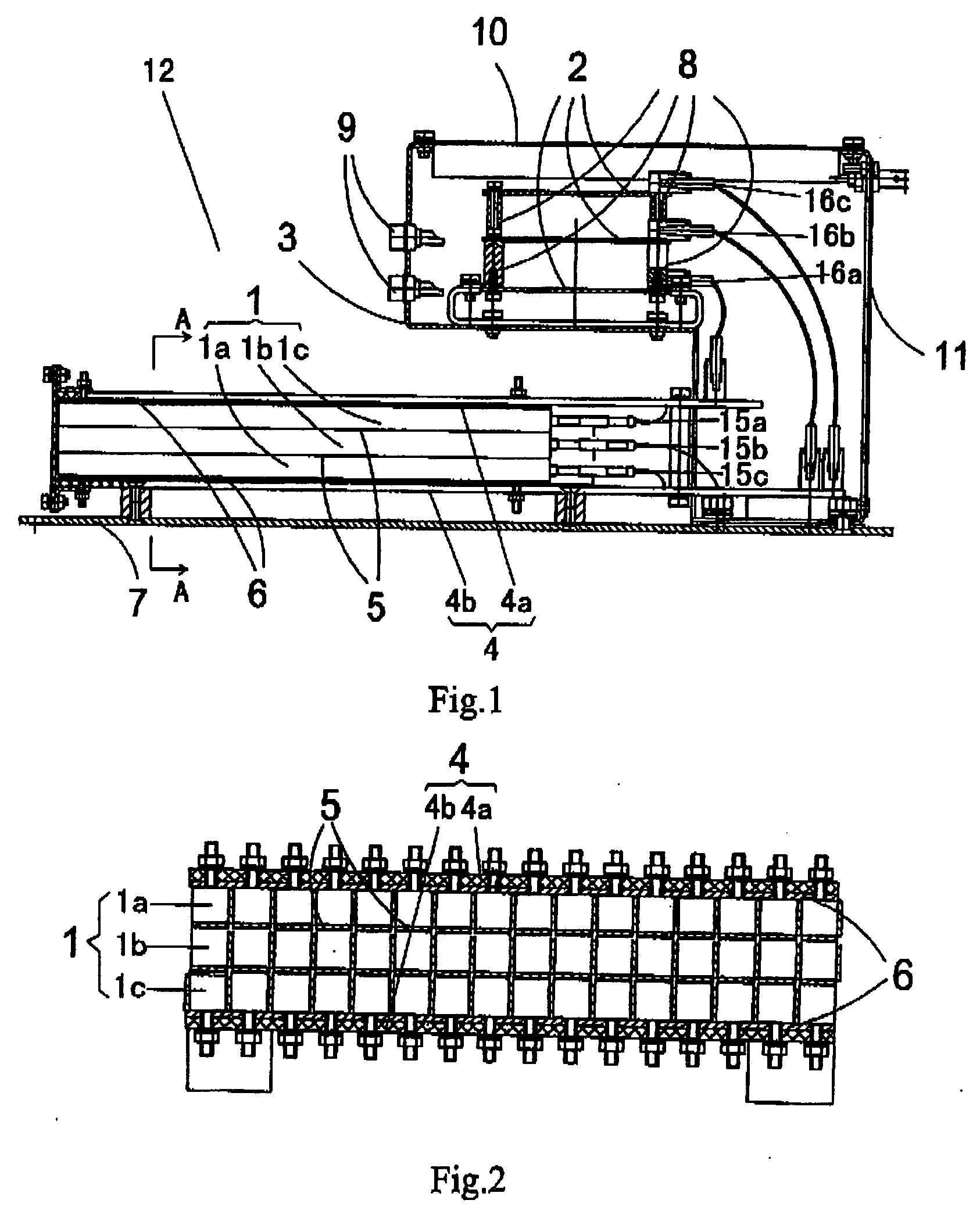
[0033] Hereafter, a preferred embodiment of the present invention will be described in detail with reference to the accompanying drawings. It should be understood that the preferred embodiment of the present invention only is illustrative and not intended to limit the protection scope of the present invention.

[0034] Referring to FIGS. 1 and 2, the multi-array detector module structure of the present invention comprises a casing 3, a bottom plate 7, and a multi-array detector 1. As shown in FIG. 1, the casing 3 has a shape. A bottom end of the casing 3 is fixed to the bottom plate 7. Inside of the casing 3, a bracket 8 is provided for fixing three circuit boards 2, and on the front end face (the upper left end shown in FIG. 1) of the casing 3, a plurality of sockets 9 are provided to connect with output terminals of the three circuit boards 2, respectively. The casing 3 is provided on the upper end face and the rear end face thereof (the right end shown in FIG. 1) with an upper cov...


PUM


Abstract

Disclosed is a multi-array detector module structure pertaining to the technical field of radiation detecting. The multi-array detector module structure comprises a casing, a bottom plate to which a bottom end of the casing is fixedly connected, and a multi-array detector composed of a plurality of detectors, wherein a mounting frame is disposed on the bottom plate, and the mounting frame includes an upper plate and a lower plate. The multi-array detector comprises two rows of peripheral detector arrays fixed to the upper plate and the lower plate of the mounting frame, respectively, and at least one row of middle detector array disposed between the two rows of peripheral detector arrays and fixed to the same. Heavy metal sheets are provided between respective detector arrays in respective rows of detector arrays, for reducing cross talk. Furthermore, heavy metal plates are provided between the two rows of peripheral detector arrays and the upper plate and the lower plate of the mounting frame, respectively, for reducing diffusion. Compared with the prior art, the present invention can achieve remarkable economic benefit by slightly improving the structure with low investment. The present invention further has advantages of a simple structure and convenience in installation and maintenance.

Description

RELATED APPLICATION [0001] This application claims priority under 35 U.S.C. 119 from Chinese Application No. 200510136318.3 filed 31 Dec. 2005, which application is incorporated herein by reference. FIELD OF THE INVENTION [0002] The present invention relates to a detector array module structure used in a radiation imaging system and a radiation imaging system having the same, and pertains to a technical field of radiation detecting. DESCRIPTION OF THE RELATED ART [0003] In the prior art, a detector array used in radiation imaging is usually arranged in a single row. Thus, manufacturing processes of a single array of detector module and image reconstruction are relatively simple. However, in a radiation system with pulse X-rays generated by an electron accelerator being used as a radiation source, in order to prevent image distortion and information loss of an object to be detected, the following conditions should be generally satisfied: a maximum speed for scanning the object to be ...

Claims


Application Information

Patent Timeline
IPC IPC(8): H05G1/60G01N23/04A61B6/00G01N23/00G21K1/12
CPCG01V5/0016
Inventor LI, YUANJINGLI, SHUWEIZHANG, QINGJUNMIAO, QINGWENDAI, ZHUDEJIANG, NIANMINGWANG, YONGQIANG
Owner NUCTECH CO LTD
Why Eureka
Try Eureka