Device for varying stitch tightness for knitting machine for hosiery or the like, particularly for circular knitting machines

a technology knitting machine, which is applied in the direction of knitting, weft knitting, textiles and papermaking, etc., can solve the problems of increasing the load of the spring or the force of the pneumatic pusher, increasing the contrast torque, and reducing the speed of varying stitch tightness, so as to achieve the effect of precise change of stitch tightness and simple manufacturing

Inactive Publication Date: 2006-06-27
SANTONI SPA
View PDF10 Cites 5 Cited by
  • Summary
  • Abstract
  • Description
  • Claims
  • Application Information

AI Technical Summary

Benefits of technology

[0015]The aim of the present invention is to solve the problems mentioned above by providing a device for varying stitch tightness for knitting machines for hosiery or the like, particularly circular knitting machines, of the type that uses an adjustment cam, which is particularly simple to manufacture and is very precise in changing stitch tightness.
[0016]Within this aim, an object of the invention is to provide a device in which the profile of the adjustment cam is simple to provide and does not require particular limitations as regards the cam followers and the cutting tools for providing the cam.
[0017]Another object of the invention is to provide a device that by avoiding the use of elastic or pneumatic pushers to maintain contact between the cam followers and the adjustment cam can use lower-power actuators to actuate adjustment cam and / or can increase the actuation speed of the adjustment cam.
[0018]Another object of the invention is to provide a device that is structurally simple and highly reliable in operation.

Problems solved by technology

For this reason, there is a tendency to increase the load of the spring or the force of the pneumatic pushers that push the cam follower against the profile of the knockover cam.
This method, aimed at eliminating the onset of plays between the profile of the adjustment cam and the cam follower, has the drawback of increasing the contrast torque that opposes the rotation of the adjustment cam and reducing the speed in varying the tightness of the knitting; to obviate this, it is necessary to use more powerful electric motors to drive the adjustment cam.
This method has the drawback that it requires the very precise machining of two separate profiles for the adjustment cams, and this can be a problem particularly as regards the synchronization of the profiles around the common rotation axis of the two cams.
This method has the drawback of requiring the provision of a convex outer profile and of a concave inner profile.
In particular, the provision of a concave profile, in addition to being more difficult, sets constraints as regards the curvature of the profile and the dimensions of the cam follower that must engage said profile and of the tool for cutting said profile.

Method used


Image

  • Device for varying stitch tightness for knitting machine for hosiery or the like, particularly for circular knitting machines
  • Device for varying stitch tightness for knitting machine for hosiery or the like, particularly for circular knitting machines
  • Device for varying stitch tightness for knitting machine for hosiery or the like, particularly for circular knitting machines

Examples


Embodiment Construction

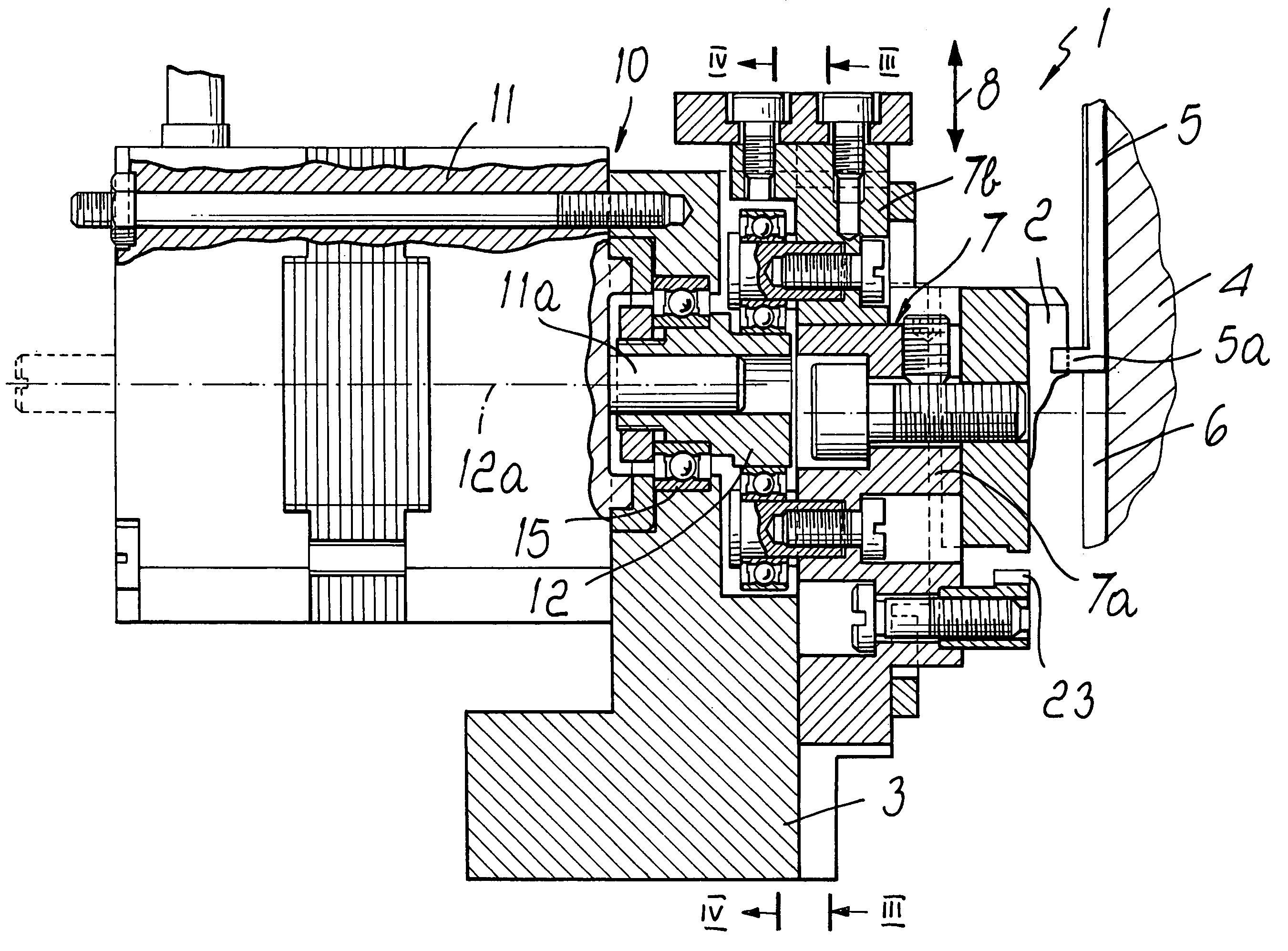
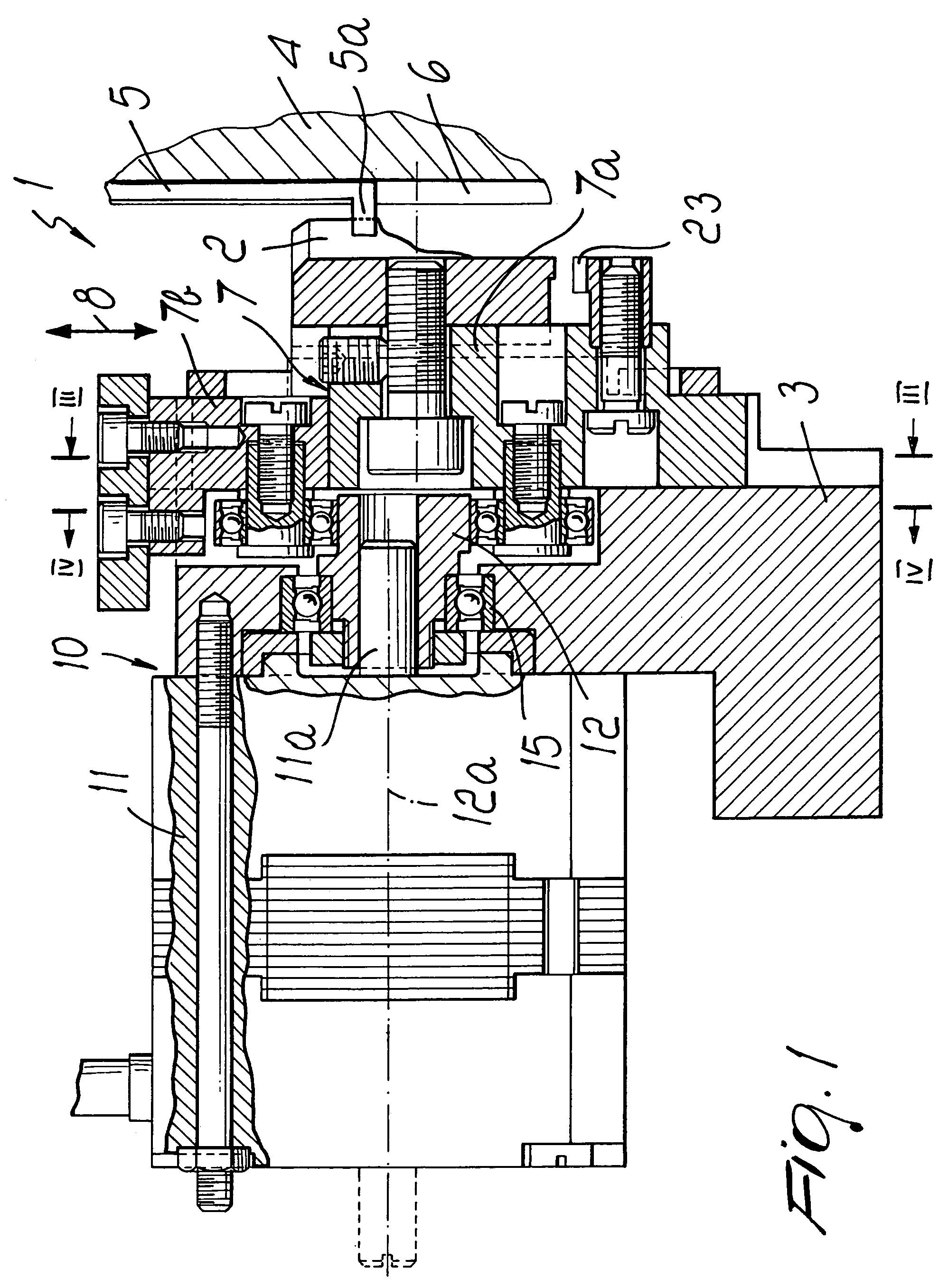
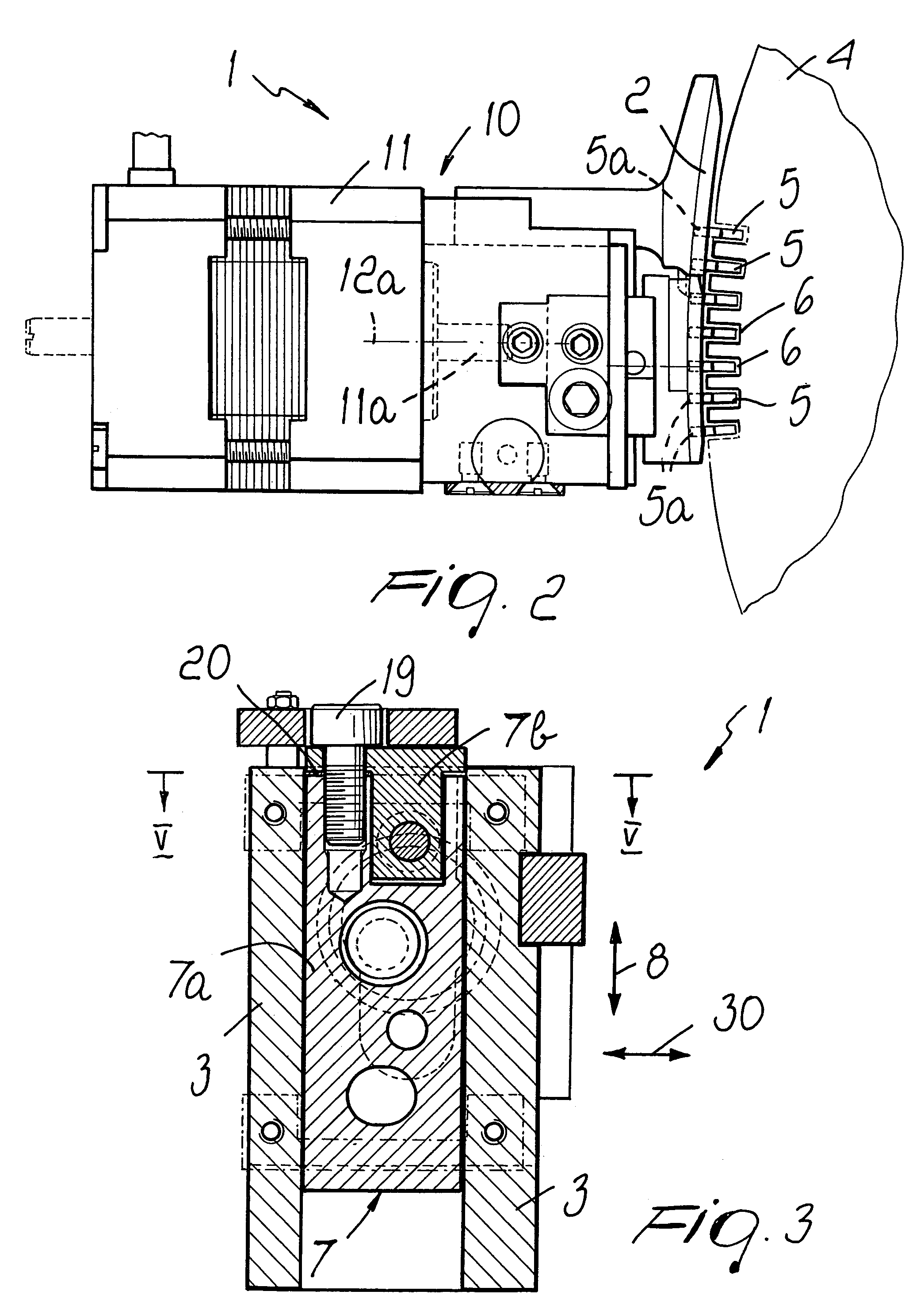
[0026]With reference to the figures, the device according to the invention, generally designated by the reference numeral 1, comprises a knockover cam 2, which is supported by a portion of the cam box 3 that faces a needle holder 4 of the hosiery knitting machine on which the device is fitted.

[0027]The knockover cam 2 has a profile that is inclined with respect to the direction of motion 30 of the needle holder 4 with respect to the cam box 3; said profile can be engaged by a heel 5a of the needles 5 or of needle pushers, which protrudes from the needle holder 4 toward the cam box 3.

[0028]The needle holder 4 has, on its face directed toward the cam box 3, a plurality of slots 6 that run substantially at right angles to the direction of motion 30 of the needle holder 4 with respect to the cam box 3; each slot accommodates a needle 5 that can slide along the corresponding slot 6.

[0029]The profile of the knockover cam 2 is adapted to produce, as a consequence of the movement of the nee...


PUM


Abstract

A device for varying stitch tightness for hosiery knitting machines, particularly for circular knitting machines, which comprises a movement adjuster connected to a slider that can slide in the cam box of the machine and supports a knockover cam of the machine. The movement adjuster comprises an actuator, connected to an adjustment cam and actuatable so as to turn the adjustment cam about its own axis through preset angles. The adjustment cam has a single external active profile, two cam followers being arranged on the slider to make contact with the active profile of the adjustment cam in two spaced points and cooperate in determining a bilateral coupling with the adjustment cam.

Description

[0001]The present invention relates to a device for varying stitch tightness for knitting machines for hosiery or the like, particularly for circular knitting machines.BACKGROUND OF THE INVENTION[0002]As is known, circular knitting machines for hosiery or the like generally comprise a needle holder, constituted by the needle cylinder and / or the dial, which faces a cam box that supports a plurality of cams for actuating the needles during the operation of the machine.[0003]More particularly, on the face of the needle holder that faces the cam box there are multiple slots, which are parallel to the axis of the needle cylinder if the needle holder is constituted by the needle cylinder or are arranged radially around the axis of the dial if the needle holder is constituted by the dial of a cylinder-and-dial circular machine. Inside each one of these slots there is a needle, which can slide along the corresponding slot in order to form knitting. The needles can be actuated directly by th...

Claims


Application Information

Patent Timeline
Patent Type & Authority Patents(United States)
IPC IPC(8): D04B15/36D04B9/46D04B15/32
CPCD04B15/327D04B15/32D04B9/46
Inventor LONATI, LEGAL REPRESENTATIVE, ETTORELONATI, LEGAL REPRESENTATIVE, FAUSTOLONATI, LEGAL REPRESENTATIVE, TIBERIOLONATI, DECEASED, FRANCESCO
Owner SANTONI SPA
Why Eureka
Try Eureka