
Linear actuator having manual override and locking mechanism

a technology of linear actuator and locking mechanism, which is applied in the direction of machines/engines, lighting and heating apparatus, heating types, etc., can solve the problems of not being able to add or otherwise vary a preload on the valve stem, and the rotation of the output coupling by hand is somewhat difficult, so as to achieve a simple and effective manner

Inactive Publication Date: 2006-06-27
TAC LLC
View PDF11 Cites 21 Cited by
  • Summary
  • Abstract
  • Description
  • Claims
  • Application Information

AI Technical Summary

Benefits of technology

[0012]In view of the above, the present invention is directed to a new and improved spring return linear actuator that includes a manual override that allows the imparting of a preload on the return spring in a simple and effective manner. Further, the invention is directed to a new and improved spring return linear actuator having such a manual override that includes a locking mechanism capable of locking the output coupling from linearly translating under influence of the return spring.
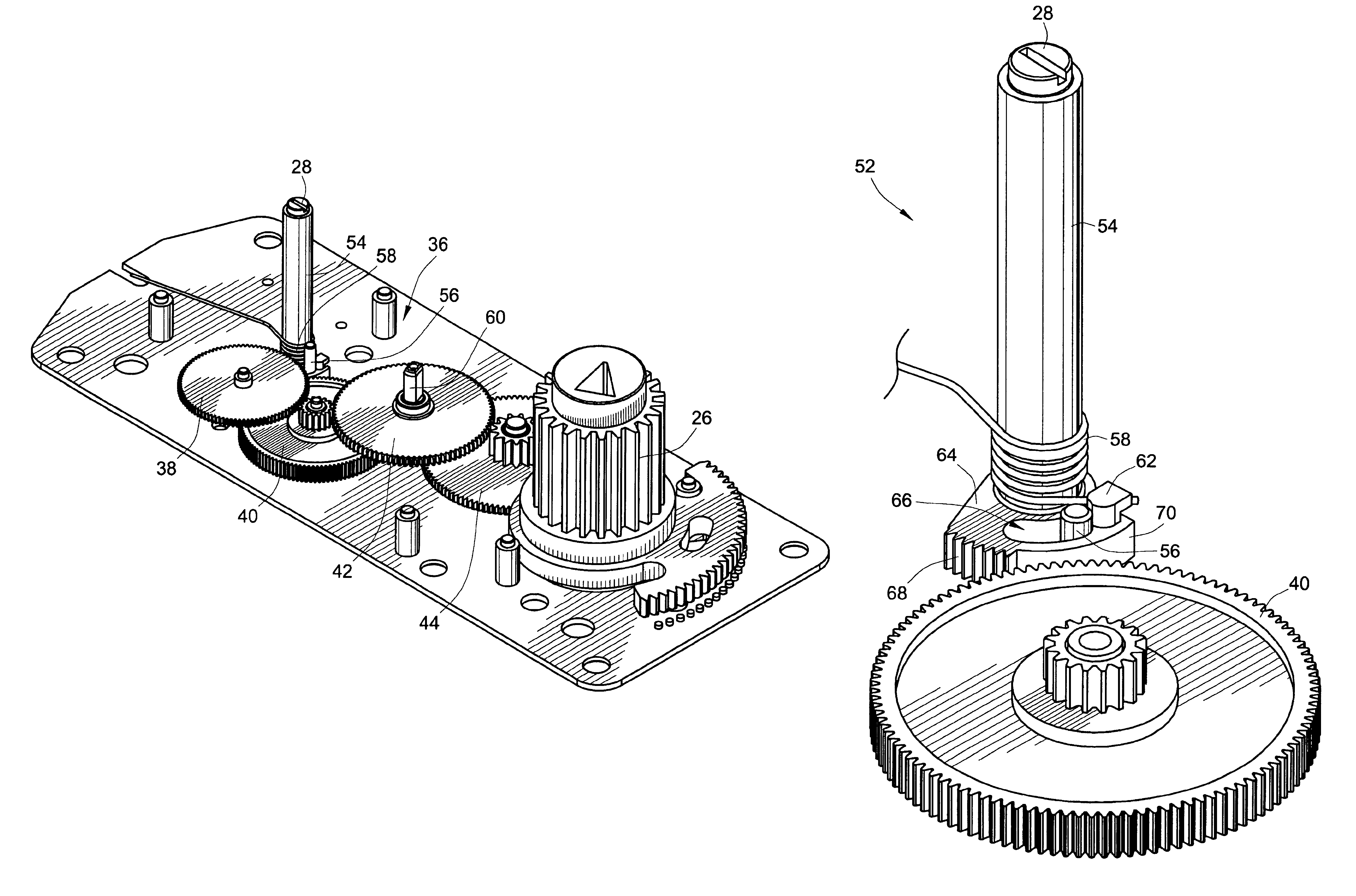
[0016]Further, the manual locking mechanism preferably includes a reset lock spring operatively coupled to the segment gear head to bias the segment gear head to the unlocked position. The segment gear head also includes a slot adapted to accommodate a stop pin. This stop pin abuts against a first end of the slot in the unlocked position and against a second end of the slot in the locked position. Rotation at a point of engagement with the locking mechanism of the gear train under influence of the clock spring is in a direction to rotate the segment gear head against the reset lock spring force. This maintains the manual locking mechanism in the locked position. Rotation at a point of engagement with the locking mechanism of the gear train under influence of the motor is in a direction to rotate the segment gear head in accord with the reset lock spring force. This aids the manual locking mechanism to achieve the unlocked position. Preferably, the motor drives the output pinion in a second rotary direction and the output rack in a second linear direction to disengage the locking mechanism from the gear train to allow rotation of the output pinion in the first rotary direction and to allow linear translation of the output rack in the first linear direction.
[0019]In yet a further alternate embodiment of the present invention, a spring return, motor driven linear actuator for driving a flow control device to an open position under power and to a closed position upon loss of power is presented. This actuator comprises a motor, a speed reducing, torque multiplying gear train drivingly coupled to an output of the motor, and an output rack and pinion drivingly coupled to the gear train. This output rack is driven in a first linear direction by the motor. A spring return mechanism including a clock spring coupled to the gear train is also included. The clock spring is wound upon energization of the motor driving the output pinion in a first rotary direction, which in turn drives the output rack in the first linear direction, and unwinds upon motor de-energization to drive the output pinion through the drive train in a second rotary direction to drive the output rack in a second linear direction. A manual override mechanism having a first user accessible interface is provided that operates in conjunction with the spring return mechanism to allow manual positioning of the output rack and winding of the clock spring. Finally, a manual locking mechanism having a second user accessible interface is also provided. This manual locking mechanism engages the gear train to prevent rotation of the output pinion in the second direction to thereby prevent linear translation of the output rack in the second direction.

Problems solved by technology

Unfortunately, since the output coupling of the actuator is coupled through a torque multiplying gear train, rotation of this output coupling by hand is somewhat difficult.
Further, since the return spring also acts through the torque multiplying gear train, holding the output coupling at the preload position while trying to connect this output coupling to the drive shaft of the driven device is also quite difficult.
Unfortunately, once the valve actuator is positioned on the valve body, there is no way to add or otherwise vary a preload on the valve stem.
However, this directly reduces the amount of linear travel of the rack that can occur during operation of the valve.
Depending on the preload force required, this may result in failure of the valve to open fully because the rack cannot be linearly translated beyond its stop.

Method used


Image

  • Linear actuator having manual override and locking mechanism
  • Linear actuator having manual override and locking mechanism
  • Linear actuator having manual override and locking mechanism

Examples


Embodiment Construction

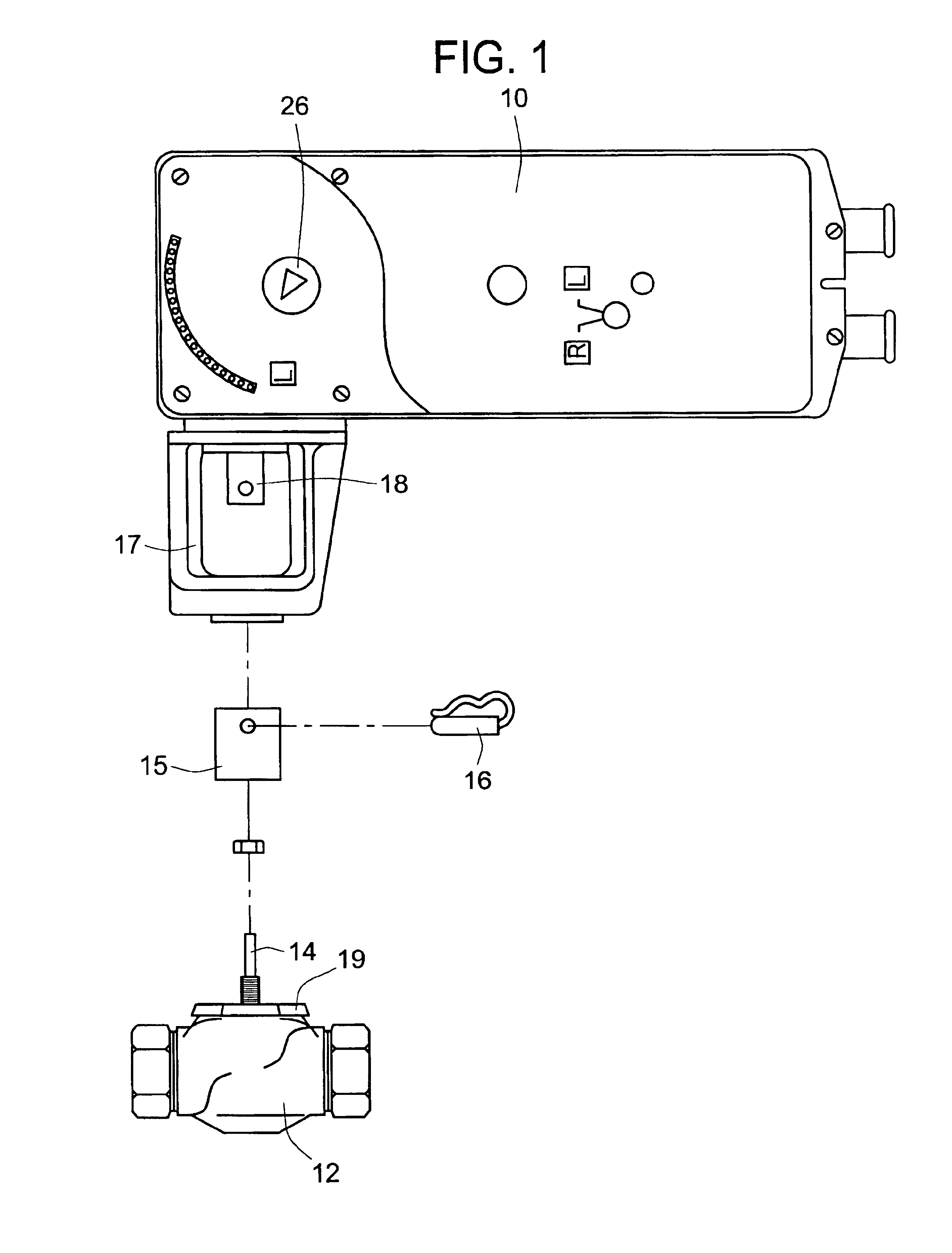
[0030]As illustrated in FIG. 1, an embodiment of the present invention is embodied in a reversible linear actuator 10 for controlling the position of a utilization device 12. In this exemplary embodiment, the utilization device 12 has been shown as being a flow control valve 12. The valve is closed and opened by linearly translating a valve stem 14 in and out relative to the valve body 12, respectively. A stem extension 15 may be used to couple the valve stem 14 to the output rack 18 of the linear actuator 10. In one embodiment, the extension 15 is coupled to the rack 18 via connecting pin 16. In a preferred embodiment, the linear actuator 10 includes a mounting bracket 17 that mates with a mounting nut 19 of the valve body 12.

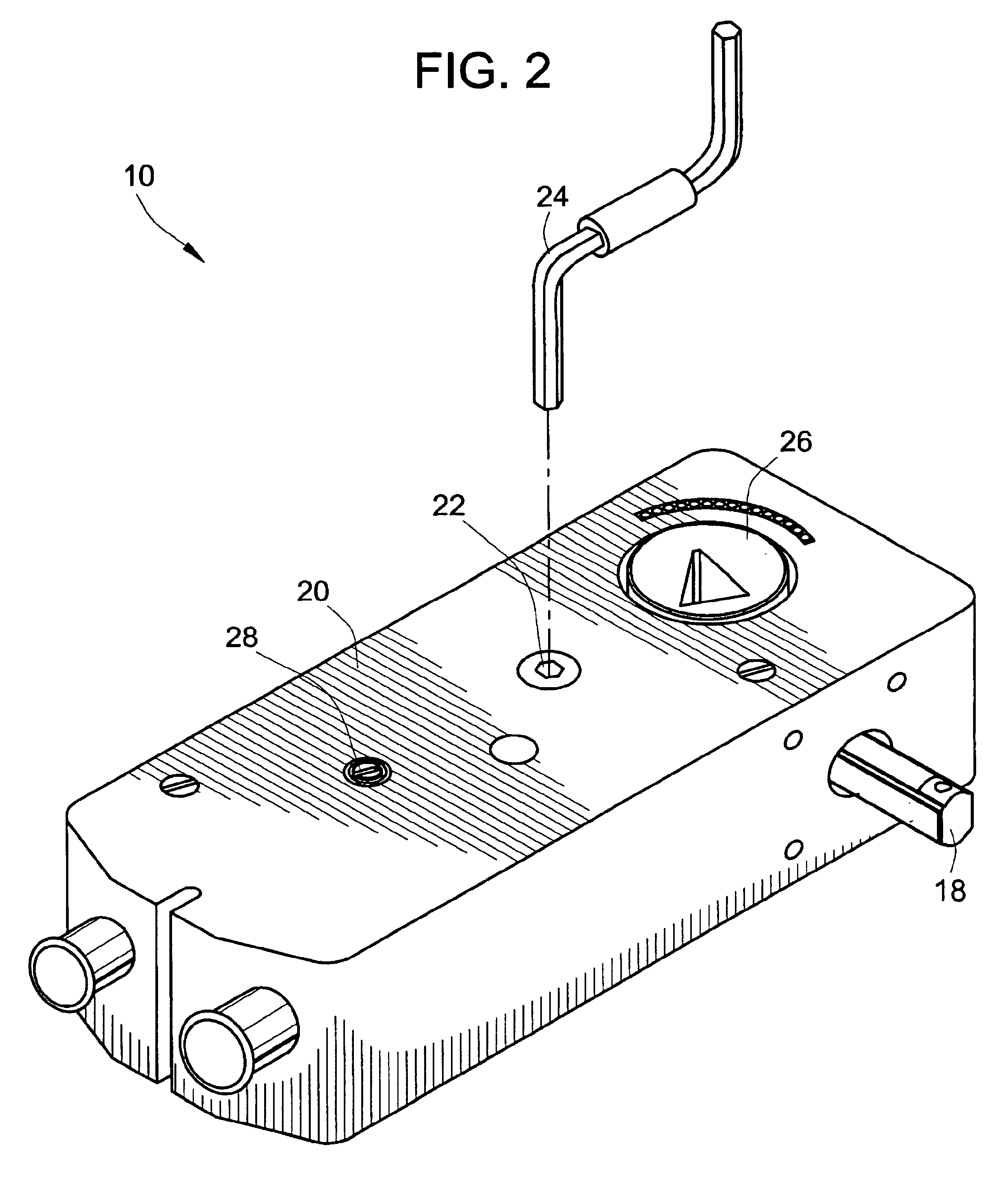
[0031]As may be seen from the enlarged view of the actuator 10 of the present invention illustrated in FIG. 2, the housing 20 of the actuator 10 includes a manual override interface 22 adapted to receive a manual override crank tool 24. Through the use of this...


PUM


Abstract

A manual override mechanism is presented for a motor-driven linear actuator that allows the output rack and pinion of the actuator to be manually positioned. Once positioned, the output may be locked by a locking mechanism to prevent this output from translating to its quiescent position. When incorporated in a spring-return linear actuator, the manual override may be used to apply a preload on the spring before the driven device is connected. When the actuator is used to drive a valve or damper, the preload applies a positive closing force on the valve or damper in its zero position to ensure a tight closure of the valve or damper. The locking mechanism engages the gear train and opposes the closing force applied by the spring return of the actuator. To disengage the locking mechanism automatically, the motor applies a forward kick to the gear train. Manual disengagement is also provided.

Description

CROSS REFERENCE TO RELATED APPLICATION[0001]This patent application is a continuation-in-part of application Ser. No. 10 / 101,681, filed Mar. 20, 2002 now U.S. Pat. No. 6,725,976 for a Manual Override and Locking Mechanism and Actuator Including Same, the teachings and disclosure of which are incorporated herein in their entireties by reference thereto.FIELD OF THE INVENTION[0002]The present invention relates generally to linear actuators, and more particularly to motor driven reversible linear actuator mechanisms that allow the manual override and position setting of the motor driven reversible linear actuator mechanisms.BACKGROUND OF THE INVENTION[0003]Motor driven actuator mechanisms for use in controlling the position of valves, dampers, etc. typically include a motor that drives an output coupling in one direction through a gear train to position the valve, damper, etc. in a desired position. Spring type or fail-safe actuator mechanisms also typically include a clock spring coup...

Claims


Application Information

Patent Timeline
IPC IPC(8): F03G1/00B05C11/02B05D3/12F16DF16K1/22F16K31/04F16K31/05F16K31/54F24F13/14
CPCF16K1/223F16K31/047F16K31/05F16K31/043F24F13/1426F16K31/54F24F2013/1433F24F2013/1473
Inventor OH, MICHAEL HUNG-SUNPARSONS, GERALD R.
Owner TAC LLC
Learn More