Fuel injection valve

a fuel injection valve and valve body technology, applied in the field of valves, can solve the problems of continuous injection, significant mechanical stress on the sealing edge and passage of the fuel injector, and the leakage of the pressure chamber, so as to minimize the leakage of the fuel injection valve

Inactive Publication Date: 2006-06-27
SIEMENS AG
View PDF7 Cites 10 Cited by
  • Summary
  • Abstract
  • Description
  • Claims
  • Application Information

AI Technical Summary

Benefits of technology

[0007]One aim of the invention is to minimize the leakage of a ...

Problems solved by technology

With the pressures which arise, the sealing edges and passages in the fuel injector are subject to significant mechanical stress, which also varies greatly during operation.
The sealing of the injection valve is therefore especially important, even with common-rail systems, since by contrast with conventional systems for periodic injection, these are permanently under system pressure in each case so that bad seals can lead to continuous injection.
A seal between the pressure chamber and the leakage chamber can only be made between spray valve body and axially moving spray valve needle by means of a sealing gap, since any type of conventional elastic seal wou...

Method used


Image

  • Fuel injection valve
  • Fuel injection valve
  • Fuel injection valve

Examples


Embodiment Construction

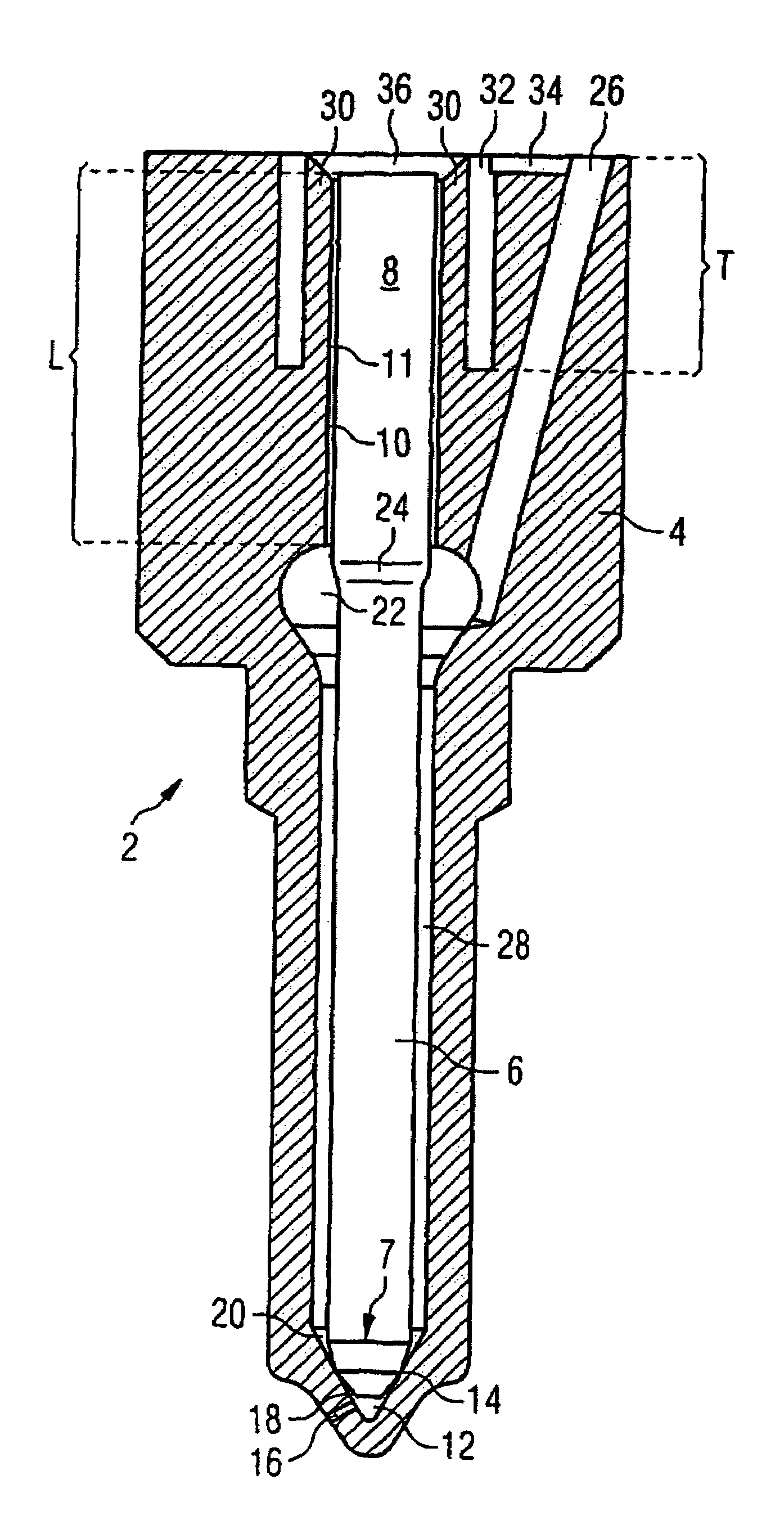
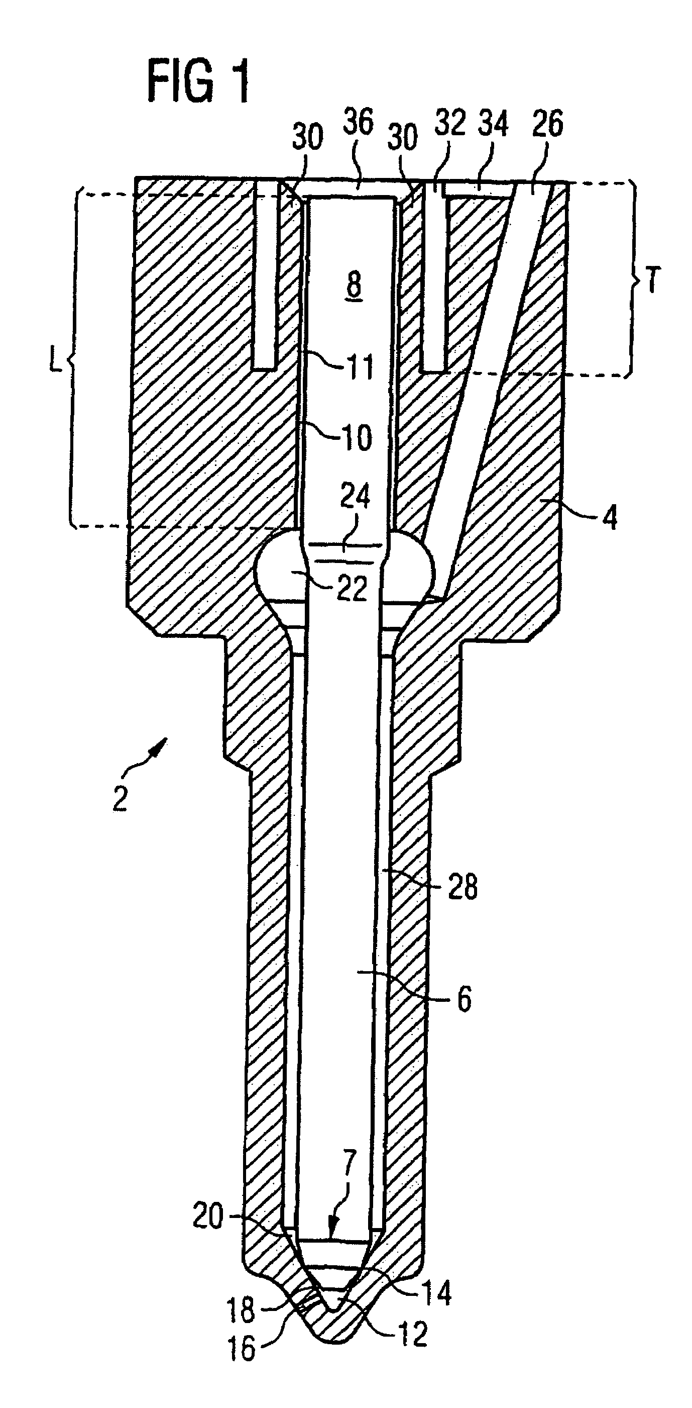
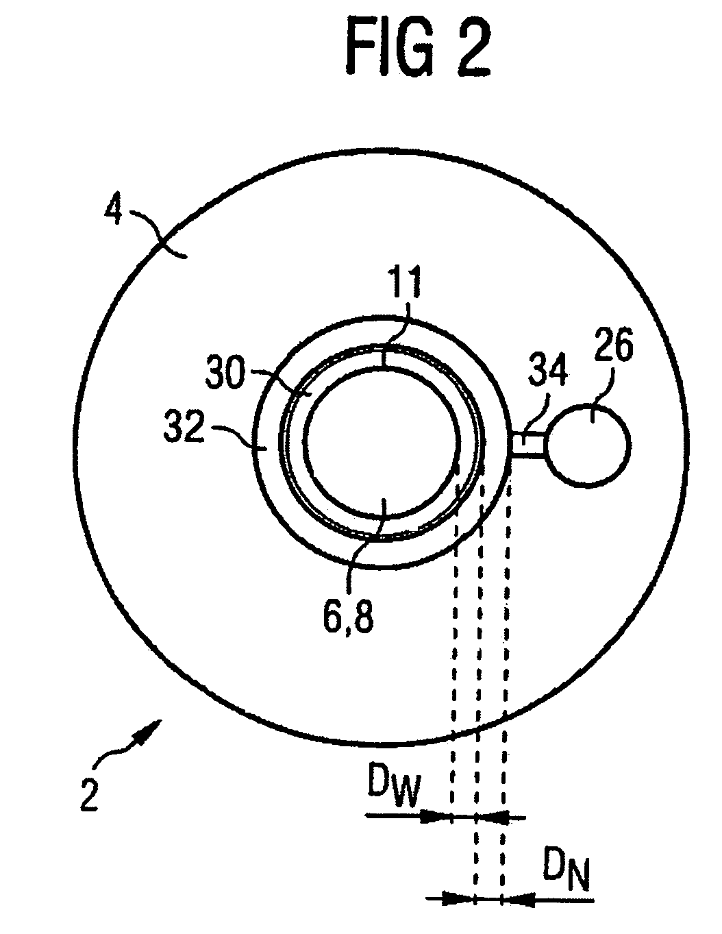
[0019]FIG. 1 shows a fuel injection valve in accordance with the invention in a schematic cross sectional view. The fuel injection valve 2 consists of a valve body 4 and a valve needle 6 which is guided sealed with a valve needle guide 8 within the valve body 4.

[0020]One or more spray orifices 16 are provided in a pocket hole 12 of the valve body 4. The valve needle 6 features a tip 7 with a seating edge 14 and a valve needle seat 18. This valve needle seat 18 sits on a valve body seat 20 thus seals the injection valve 2 with the spray orifices 16.

[0021]Via the fuel inlet 26 and a circular pressure chamber 22 lying between the valve needle 6 and the valve body 4 the fuel reaches the seat edge 14 and with valve needle 6 lifted, passes along the circular chamber 28 between valve needle 6 and valve body on via the pocket hole 12 and the spray orifice 16 into the combustion chamber of the internal combustion engine.

[0022]Between a cylinder-shaped valve needle guide 8 in the upper area o...


PUM


Abstract

The invention relates to a valve, in particular a fuel injection valve for a high-pressure accumulator injection system of an internal combustion engine. Said valve comprises a valve body, provided with a valve body seat and a valve needle, guided over a guiding length in said valve body within a stationary circular cylindrical guiding surface and provided with a valve needle seat for controlling a spray orifice. According to the present invention, a pressure reservoir under high pressure, in the shape of an annular groove arranged coaxially in relation to the guiding surface, is provided in said valve body.

Description

CROSS-REFERENCE TO RELATED APPLICATION[0001]This application is a continuation of co-pending International Application No. PCT / DE02 / 03628 filed Sep. 25, 2002 which designates the United States, and claims priority to German application number DE10147792.9 filed Sep. 27, 2001.TECHNICAL FIELD OF THE INVENTION[0002]The invention relates to a valve, in particular a fuel injection valve for a high-pressure accumulator injection system of an internal combustion engine.BACKGROUND OF THE INVENTION[0003]With conventional fuel injectors for injection systems of internal combustion engines the fuel injection nozzle is typically controlled by means of a valve needle, which is arranged to form a moving seal within a guide in a valve body of an injection valve. The valve needle features a valve needle seat at its tip, which, together with a valve body seat of the valve body, opens or closes at least one spray orifice to the combustion chamber of the internal combustion engine. The at least one sp...

Claims


Application Information

Patent Timeline
IPC IPC(8): F02M47/02F02M59/00F02M61/00F02M61/10F02M63/00F02M47/00F02M61/12F02M61/16
CPCF02M61/12F02M61/168F02M2200/16
Inventor ASTACHOW, ANDREJKRUGER, GRIT
Owner SIEMENS AG
Why Eureka
Try Eureka