Method of operating a direct dme fuel cell system

a fuel cell and direct technology, applied in the direction of fuel cells, fuel cell auxiliaries, electrochemical generators, etc., can solve the problems of methanol toxic, loss of voltage and overall performance, and limited use of nafion® membranes

Inactive Publication Date: 2012-10-25
DANMARKS TEKNISKE UNIV
View PDF6 Cites 6 Cited by
  • Summary
  • Abstract
  • Description
  • Claims
  • Application Information

AI Technical Summary

Benefits of technology

[0055]The method according to the present invention may be used for numerous transportation or stationary applications such a...

Problems solved by technology

For the same reason, use of Nafion® membranes is usually limited to an operating temperature of up to 80° C. at atmospheric pressure.
A typical DMFC is fed with a liquid methanol-water mixture at temperatures of up to 80° C. A major problem of methanol-driven fuel cells is diffusion of methanol through the proton exchange membrane.
This fuel crossover may lead to oxidation of methanol at the cathode and resulting loss of voltage and overall performance.
In addition, methanol is toxic.
This process requires energy and the utilization of special catalysts, thereby increasing complexity and cost.
Another problem of DME reforming, or reforming of any carbon-containing fuel, is the presence of carbon monoxide, CO, which can poison Pt catalysts already at concentrations of a few tens of ppm.
Furthermore, impurities found in fuels, such as CO, constitute a major problem for fuel cell performance particularly at temperatures below 100° ...

Method used


Image

  • Method of operating a direct dme fuel cell system
  • Method of operating a direct dme fuel cell system

Examples


example 1

Preparation of Membrane Electrode Assembly

[0056]The electrodes, a PtRu / C anode and a Pt / C cathode, were produced by tape-casting. A carbon paper anode was loaded by use of a 60% 2:1 Pt—Ru catalyst powder (Platinum, nominally 40%, Ruthenium, nominally 20% on carbon black; Alfa Aesar GmbH & Co KG) added to a PBI solution (4% wt in N,N-dimethylacetamide, DMAc) using amounts resulting in a loading of 1.5 mg Pt—Ru per cm2 and 0.3 mg PBI per cm2. A carbon paper cathode was loaded by use of a 38.6% Pt catalyst (powder, prepared by reduction of Pt from a hexacloroplatinate solution) added to a PBI solution (4% wt in N,N-dimethylacetamide, DMAc) using amounts resulting in a loading of 0.7 mg Pt per cm2 and 0.3 mg PBI per cm2. After drying, doping of PBI was performed using a phosphoric acid solution for establishing an acid doping level of 6.

[0057]The MEA was obtained by hotpressing the electrodes on either side of a phosphoric-acid-doped PBI membrane produced by solution casting (acid d...

example 2

Performance at Different Temperatures

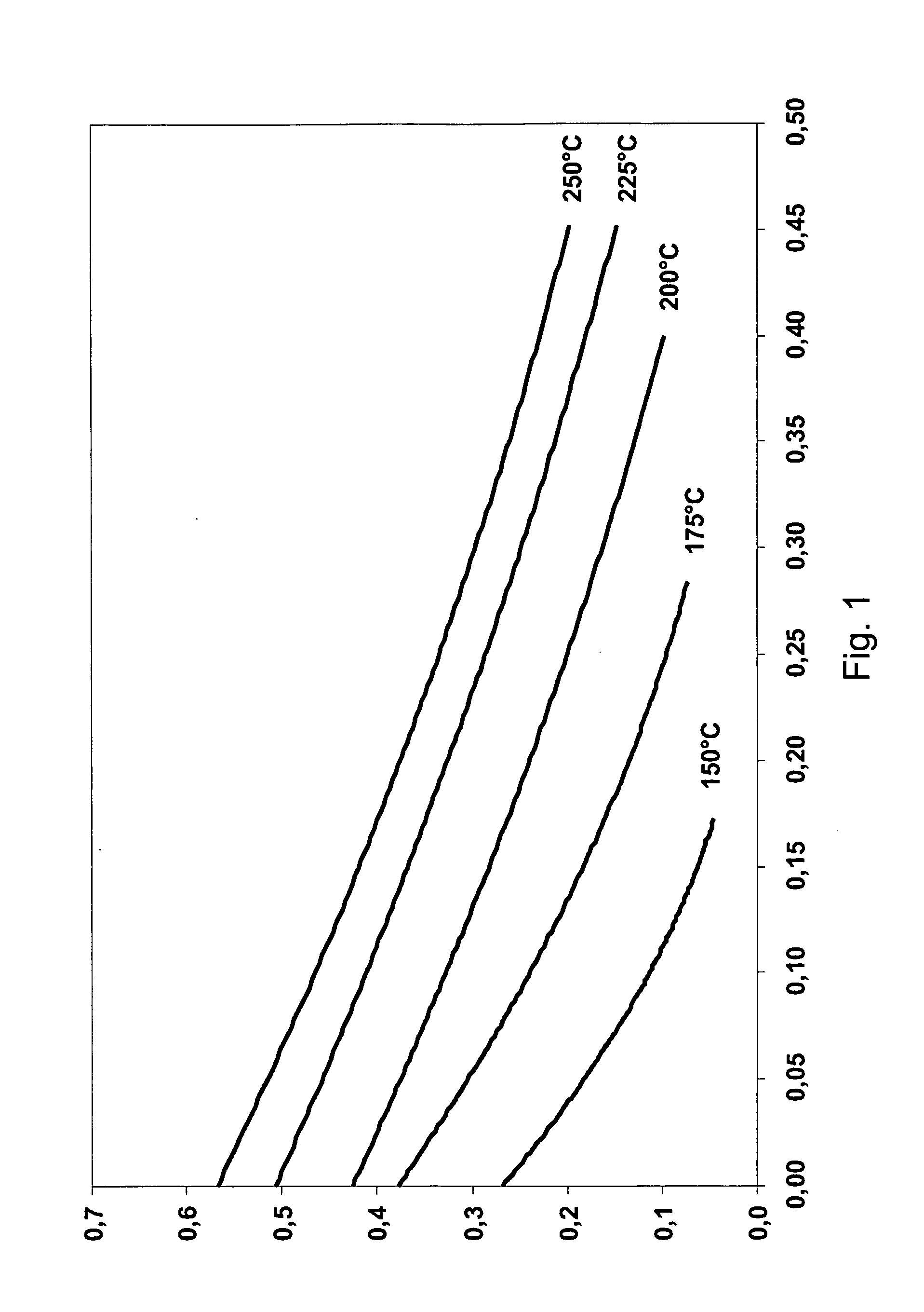
[0058]Polarisation curves were obtained at 150, 175, 200, 225 and 250° C. Peak power densities at different temperatures are shown in table 1.

TABLE 1Maximum power densityTemperature (° C.)(mW / cm2)1501217529200522257825096

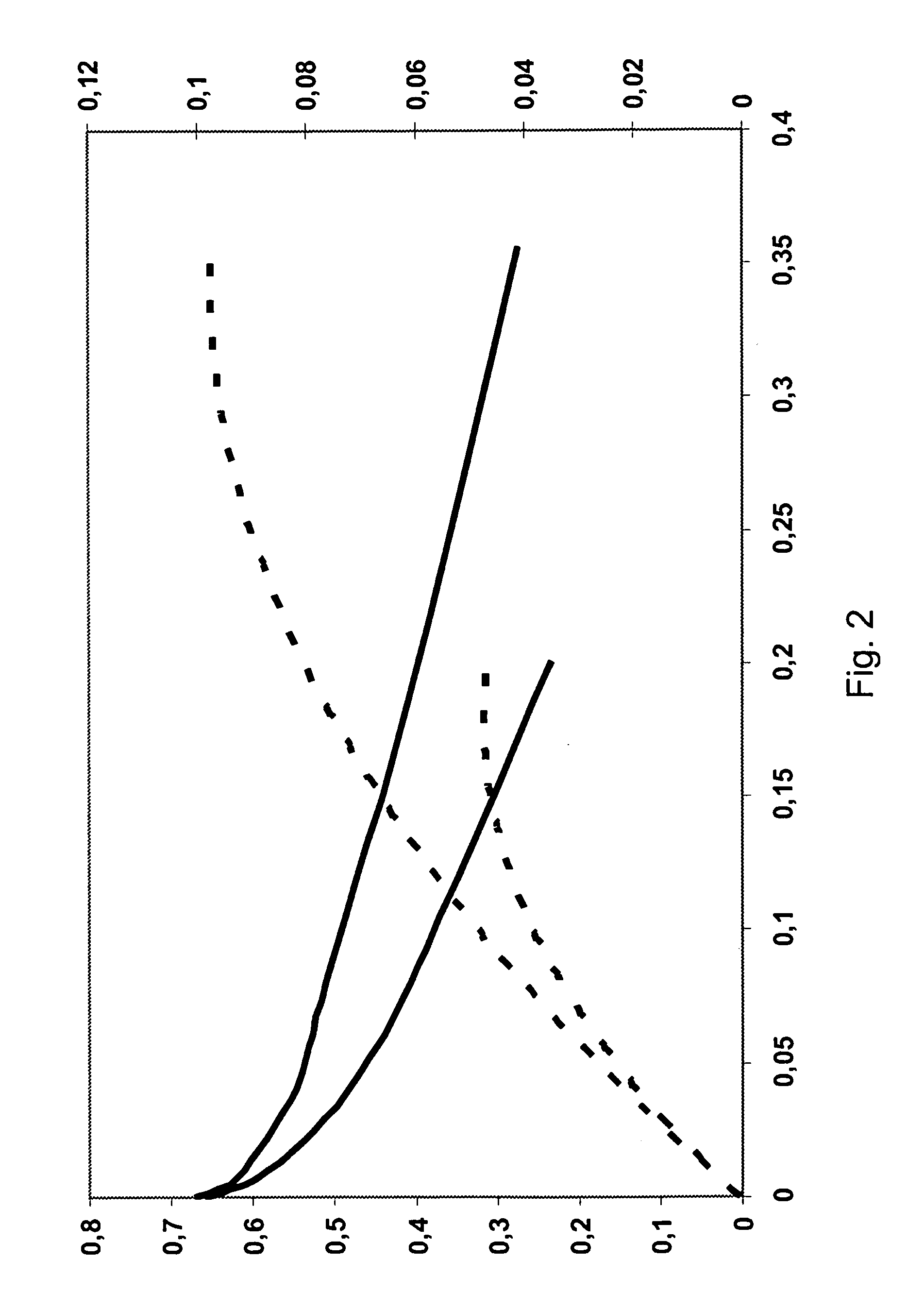
[0059]At 200° C., the cell had the lowest ohmic resistance. At temperatures of 200° C. or above, the ohmic loss remains constant. After an operating time of one hour, the maximum power densities were further increased to values of about 100 mW / cm2 at 200° C. and at an equivalence ratio of between 1.1 and 1.5. Open circuit voltages (OCVs) were about 0.7 V.

[0060]Exemplary polarisation curves are shown in FIGS. 1 and 2, where FIG. 1 shows results from an early experiment and FIG. 2 shows test results from a later experiment.

example 3

Membrane Crossover of DME and Methanol

[0061]Air was evacuated from a first gas chamber and to a second gas chamber separated from each other by a phosphoric-acid-doped PBI membrane (acid doping: 6, thickness: 50 μm). The resulting absolute pressure inside both chambers was below 20 mbar. Subsequently, either gaseous methanol or DME was injected into the first gas chamber. The starting pressure of DME was 4 bar, and the starting pressure for methanol was 6 bar. The rate of gas transport across the membrane was determined by recording the pressure build up in the second gas chamber over time.

[0062]The membrane permeabilities were calculated as 7.4*10−9 mol cm−1 s−1 bar−1 for DME and 10.4*10−9 mol cm−1 s−1 bar−1 for methanol. Thus, methanol diffuses through the membrane at a rate that is about 40% higher than the rate of DME diffusion.


PUM


Abstract

The present invention relates to a method of operating a fuel cell system comprising one or more fuel cells with a proton exchange membrane, wherein the membrane is composed of a polymeric material comprising acid-doped polybenzimidazole (PBI). The method comprises adjusting the operating temperature of the fuel cell to between 120 and 250° C., supplying an oxidant stream to the cathode, and supplying a humidified fuel stream to the anode, said fuel stream comprising dimethyl ether, wherein dimethyl ether is directly oxidised at the anode.

Description

TECHNICAL FIELD[0001]The present invention relates to a method of operating a fuel cell system.BACKGROUND OF THE INVENTION[0002]Fuel cells are currently viewed as promising energy conversion systems that may replace traditional, less efficient power generation technology. Fuel cells convert the chemical energy of a given fuel directly into electrical energy leading to a higher degree of efficiency as compared to power generation employing a conventional heating cycle. Furthermore, fuel cells generally have no moving mechanical parts, thereby reducing operational noise levels. Consequently, fuel cell systems are today feasible for a large range of industrial applications. Although often still used at demonstration level, fuel cell technology is on the verge of becoming a competitive alternative to traditional power generation.[0003]Among the different types of fuel cells, proton exchange membrane fuel cells (PEMFC) have received considerable attention. The proton exchange membrane is...

Claims


Application Information

Patent Timeline
IPC IPC(8): H01M8/04H01M8/06H01M8/10
CPCH01M8/1009Y02E60/521H01M2300/0082H01M8/103Y02E60/50H01M8/04992
Inventor JENSEN, JENS OLUFLI, QINGFENGBJERRUM, NIELS J.STEENBERG, THOMAS
Owner DANMARKS TEKNISKE UNIV
Why Eureka
Try Eureka