Polishing apparatus and related polishing methods
- Summary
- Abstract
- Description
- Claims
- Application Information
AI Technical Summary
Benefits of technology
Problems solved by technology
Method used
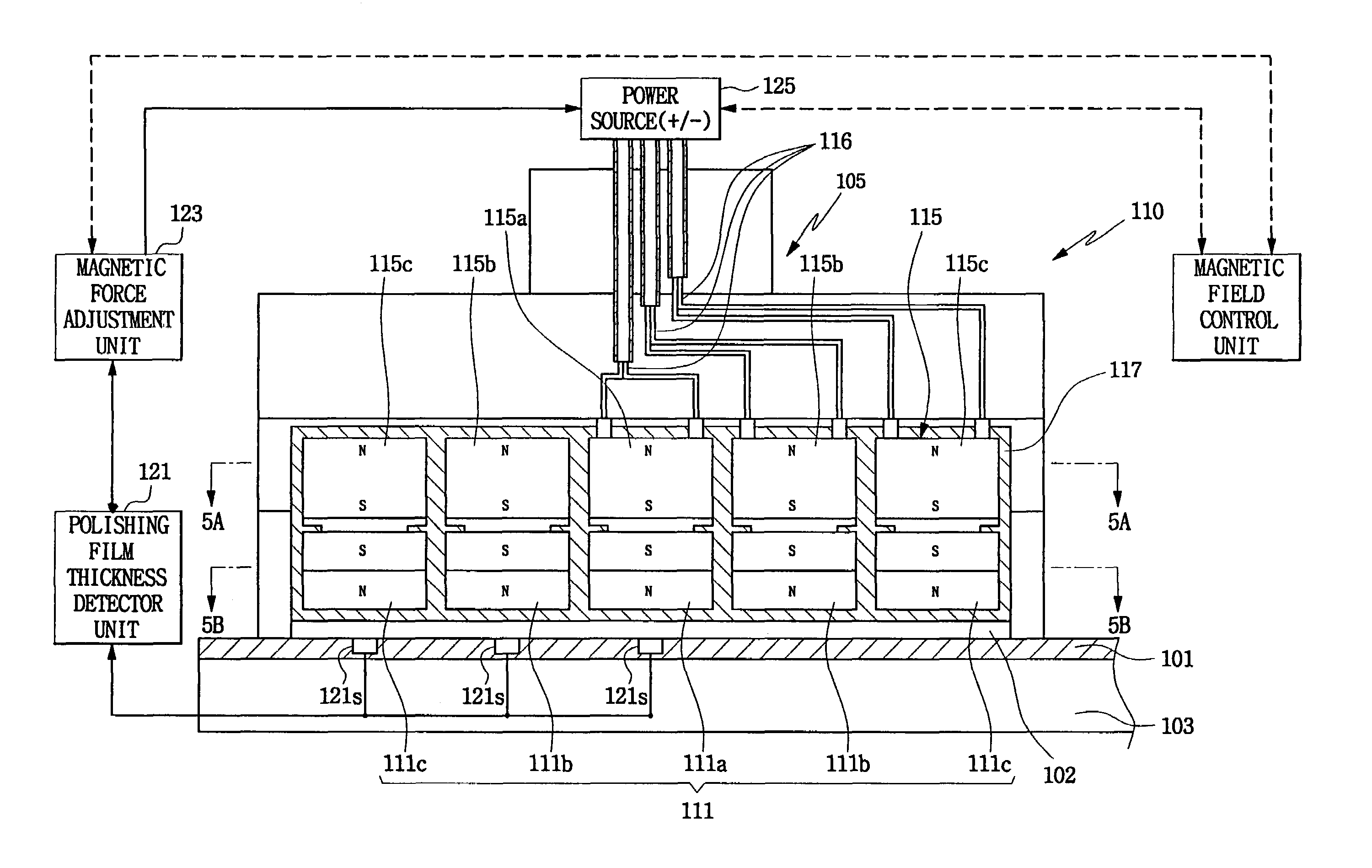
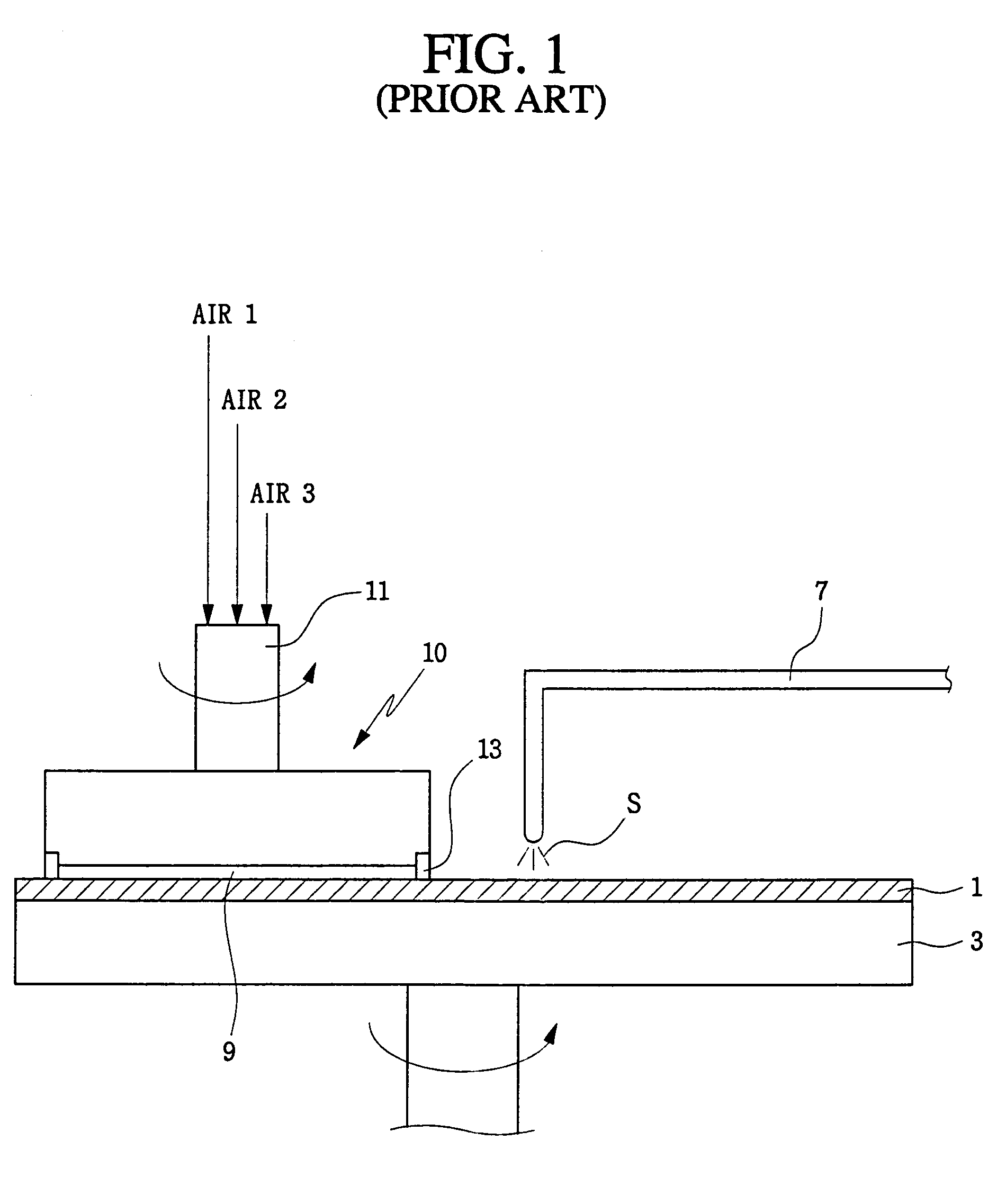
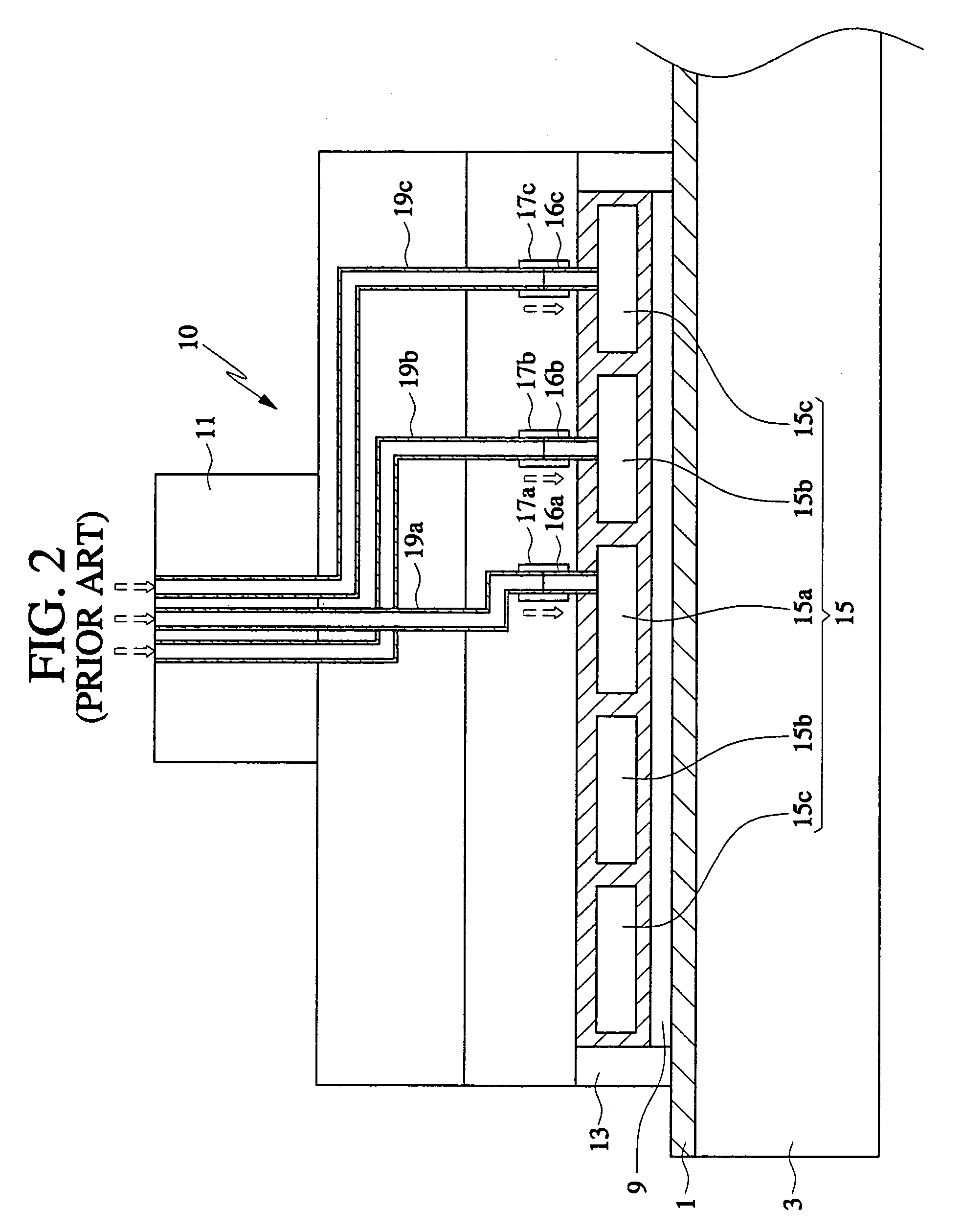
Image

Examples
Embodiment Construction
[0036]The present invention will now be described more fully hereinafter with reference to the accompanying drawings, in which embodiments of the invention are shown. Like numbers refer to like elements. In the figures, certain features, layers or components may be exaggerated for clarity. Also, in the figures, broken lines indicate optional features or components unless stated otherwise. When a layer is referred to as being “on” another layer or substrate, it can be directly on the other layer or substrate, or intervening layers, films, coatings and the like may also be present unless the word “directly” is used which indicates that the feature or layer directly contacts the feature or layer. In addition, spatially relative terms, such as “beneath”, “below”, “lower”, “above”, “upper” and the like, may be used herein for ease of description to describe one element or feature's relationship to another element(s) or feature(s) as illustrated in the figures. It will be understood that ...
PUM
| Property | Measurement | Unit |
|---|---|---|
| Thickness | aaaaa | aaaaa |
| Polarity | aaaaa | aaaaa |
| Magnetic field | aaaaa | aaaaa |
Abstract
Description
Claims
Application Information
 - Generate Ideas
- Intellectual Property
- Life Sciences
- Materials
- Tech Scout
- Unparalleled Data Quality
- Higher Quality Content
- 60% Fewer Hallucinations
Browse by: Latest US Patents, China's latest patents, Technical Efficacy Thesaurus, Application Domain, Technology Topic, Popular Technical Reports.
© 2025 PatSnap. All rights reserved.Legal|Privacy policy|Modern Slavery Act Transparency Statement|Sitemap|About US| Contact US: help@patsnap.com