Apparatus for use in regenerating adsorbent

a technology for regenerating adsorbent and apparatus, which is applied in the direction of liquefaction, lighting and heating apparatus, and separation processes, etc. it can solve the problems of difficulty in filling the adsorbent vessel with adsorbent, difficulty in heating maintenance access, and large time-consuming for gas heated in the heater to reach, so as to improve the mixing and uniformity of heating, reduce the time of regeneration cycle, and reduce the effect of heating tim

Inactive Publication Date: 2006-06-27
AIR PROD & CHEM INC
View PDF45 Cites 42 Cited by
  • Summary
  • Abstract
  • Description
  • Claims
  • Application Information

AI Technical Summary

Benefits of technology

[0019]The ratio of the gas velocity over the heater elements to the superficial vessel velocity in the adsorber vessel further differentiates the preferred arrangement according to the invention from the use of heater elements within the adsorber vessels and provides improved mixing and uniformity of the heating of the regenerating gas, and hence the adsorbent, providing a high heat transfer co-efficient between the heater elements and the regenerating gas.
[0020]The location of the heater elements within an inlet nozzle connecting to the adsorber vessel rather than at a remote location connected to the adsorber vessel via pipe and valve work constituting a manifold ensures that the heat applied to the regenerating gas is much more quickly communicated to the adsorbent in a much better ordered and shaped heat pulse enabling the minimising of the regeneration cycle time.

Problems solved by technology

As we have now appreciated, both of these arrangements have significant disadvantages.
Where a common heater is positioned on the other side of a manifold connecting to both adsorber vessels, it takes a considerable period of time for gas heated in the heater to reach and begin to heat the adsorbent in the beds.
On the other hand, where the heater is installed in the adsorbent containing vessel itself this gives rise to difficulties in access for heater maintenance and difficulties in filling the adsorber vessels with adsorbent.
It also gives rise to difficulty due to lack of mixing, maldistribution and less than optimum heat transfer in ensuring that each particle of adsorbent is heated to an adequate temperature for full regeneration.
Adsorbent materials are not characterised by high thermal conductivity and the heat transfer coefficient between the gas and the adsorbent is poor.
However, all of these direct heating methods suffer from the difficulties discussed above.

Method used


Image

  • Apparatus for use in regenerating adsorbent
  • Apparatus for use in regenerating adsorbent
  • Apparatus for use in regenerating adsorbent

Examples


Embodiment Construction

[0041]The invention will be further described and illustrated with reference to the accompanying drawings in which:

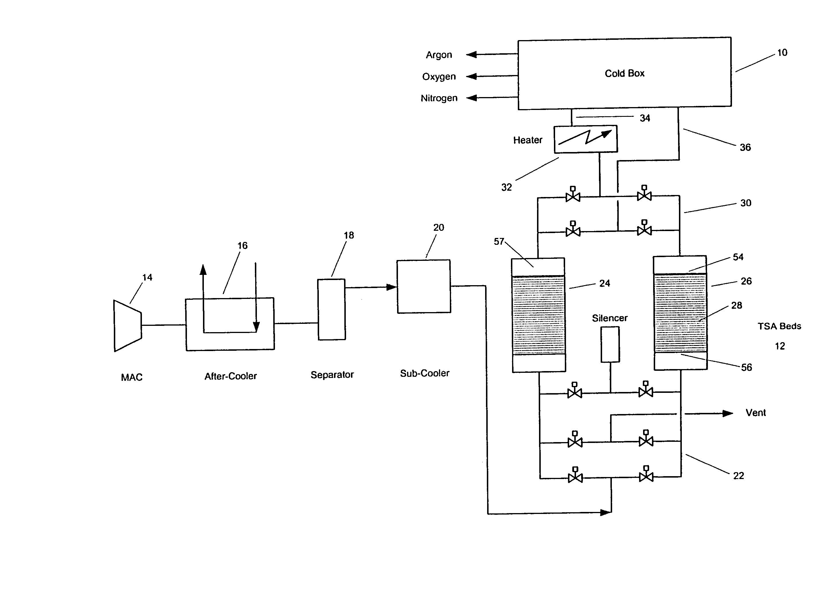
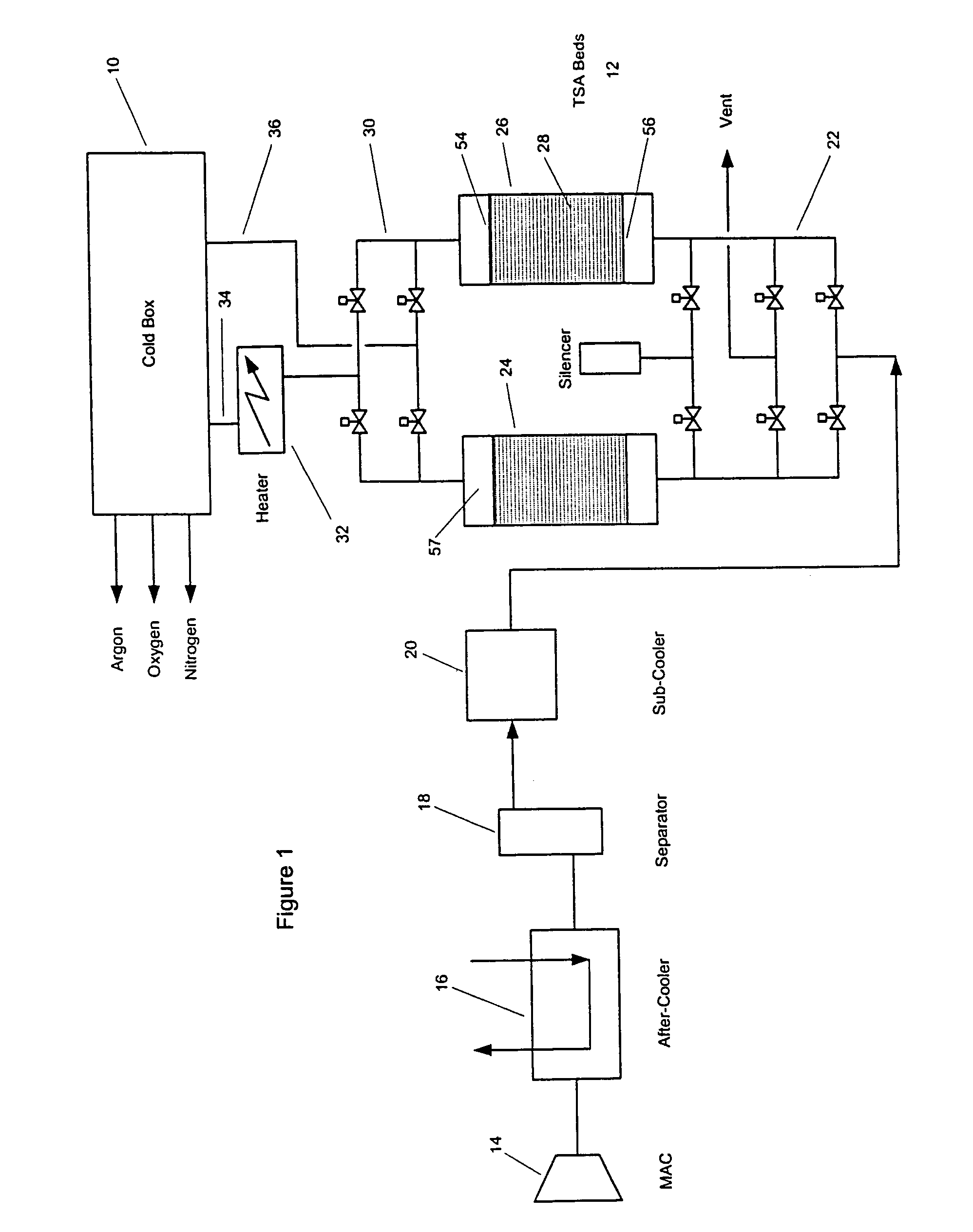
[0042]FIG. 1 shows a typical TSA pre-separation purification unit attached to a cryogenic air separation apparatus;

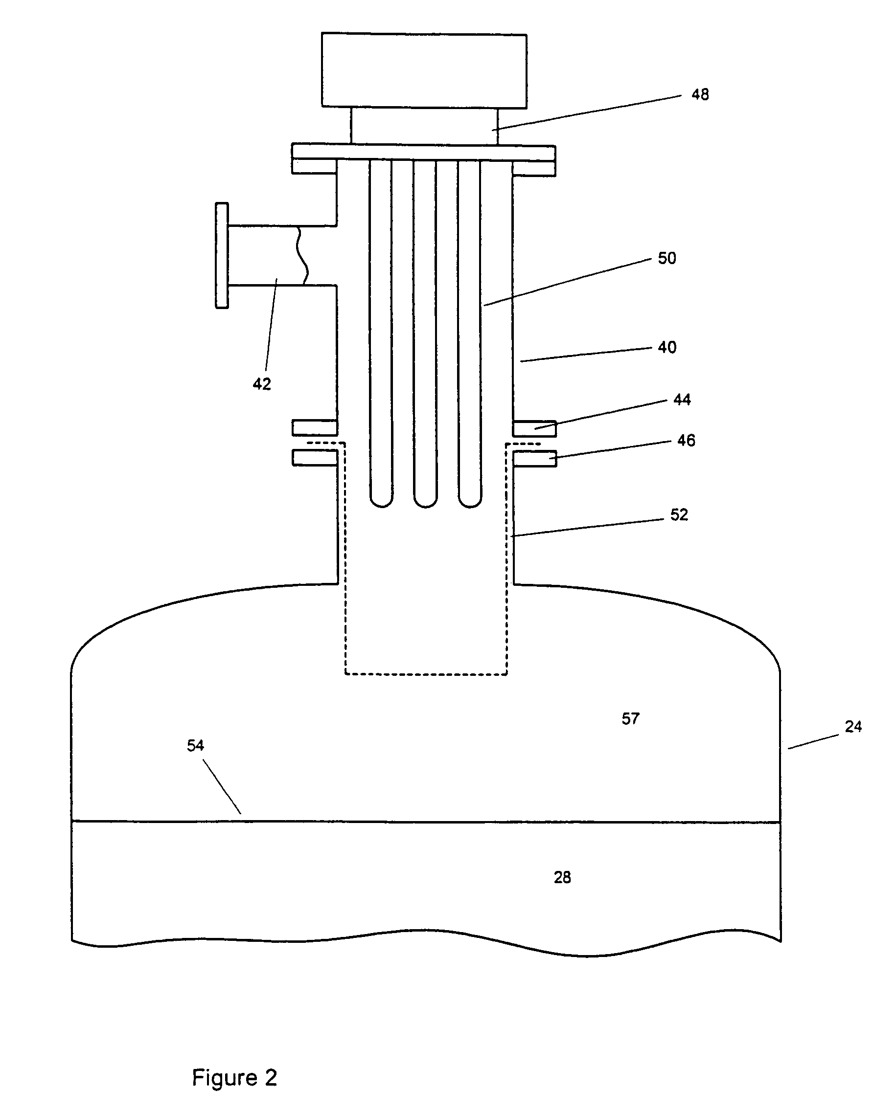
[0043]FIG. 2 shows a schematic longitudinal cross-sectional view of one end of an adsorber vessel according to the invention;

[0044]FIG. 3 shows in a manner similar to FIG. 2 a variant of the apparatus of FIG. 2 in which the adsorbent bed is a radial flow bed; and

[0045]FIG. 4 shows in half section a variant of the apparatus of FIG. 2 employing an alternative type of heater.

[0046]Although the invention is broadly applicable to the separation of gas components from gas mixtures by a swing adsorption process, we shall exemplify it in the following description by reference to the pre-purification of air by the removal of water, carbon dioxide and other more minor contaminants prior to cryogenic air separation.

[0047]The cryogenic purification of air requires a pr...


PUM


Abstract

An adsorber vessel for use in the adsorption of a component from a gas and subsequent regeneration by thermally induced desorption of the component comprises an inlet for regeneration gas having an inlet nozzle containing at least one heater element, and an outlet for regeneration gas, the inlet and outlet for regeneration being separated by a flow path including a flow chamber containing a body of adsorbent, and wherein the body of adsorbent has a first end which is adjacent the inlet for regeneration gas and a second end which is remote from the inlet for regeneration gas, and the or each heater element is located so as not to penetrate through the first end of the body of adsorbent.

Description

BACKGROUND OF THE INVENTION[0001]The present invention relates to adsorber vessels for use in the adsorption of components from gases and subsequent regeneration of the adsorbent by thermally induced desorption of adsorbed components. It further relates to apparatus for use in the removal of components from gas mixtures by swing adsorption including temperature swing adsorption and related techniques and thermally assisted pressure swing adsorption as well as methods for the operation of such apparatus, including the pre-purification of air prior to cryogenic distillation.[0002]It is necessary in a number of circumstances to remove gas components from a gas stream by adsorption on a solid adsorbent, with periodic regeneration of the adsorbent. The removed gas components may be of intrinsic value or they may be contaminating components in the gas mixture.[0003]In such methods the gas stream is conventionally fed in contact with a solid adsorbent contained in an absorber vessel to ads...

Claims


Application Information

Patent Timeline
Patent Type & Authority Patents(United States)
IPC IPC(8): B01D53/047B01D53/04B01D53/26F25J3/04
CPCB01D53/0423B01D53/0431Y02C20/10B01D53/0438B01D53/0462B01D53/261B01D2256/10B01D2256/12B01D2257/402B01D2257/504B01D2257/702B01D2257/80B01D2259/40077B01D2259/4009B01D2259/402B01D2259/416B01D2259/652Y02C10/08F25J3/04181F25J2205/70Y02C20/40
Inventor HABEN, CHRISTOPHER RICHARDKALBASSI, MOHAMMAD ALIO'CONNOR, DECLAN PATRICK
Owner AIR PROD & CHEM INC
Why Eureka
Try Eureka