Operational transconductance amplifier input driver for class D audio amplifiers

a transconductance amplifier and input driver technology, applied in the field of audio amplifiers, can solve the problems of increasing the bias current at the audio output, boosting any noise and offset voltage, and theoretically less efficient ab amplifiers

Active Publication Date: 2006-06-27
TEXAS INSTR INC
View PDF14 Cites 74 Cited by
  • Summary
  • Abstract
  • Description
  • Claims
  • Application Information

AI Technical Summary

Benefits of technology

[0017]It is a further object of this invention to provide such an architecture in which the amplifier standby current is minimized, along with reduced turn-on “popping” and a lower noise floor characteristic.
[0019]It is a further object of this invention to provide such an architecture in which the output characteristic is highly linear, so that total harmonic distortion is minimized.
[0021]The present invention may be implemented into an audio preamplifier circuit utilizing an operational transconductance amplifier (OTA). A feedback loop is incorporated into the OTA preamplifier. The transconductance of the OTA is set by an input resistor in series with a DC blocking capacitor, eliminating the output current due to input offset voltage.

Problems solved by technology

While the non-zero bias current renders class AB amplifiers theoretically less efficient than class B amplifiers, class AB amplifiers present avoid the crossover distortion of class B amplifiers.
While this conventional preamplifier and amplifier arrangement of FIG. 1 has been well-accepted in the industry, it inherently boosts any noise and offset voltage that appears at the output of preamplifier 5.
This offset boost results in increased bias current at the audio output, a higher noise floor, and louder “popping” as the amplifier is turned on.
However, this is impractical due to the very large slew rate required to charge and discharge these large capacitors in handling high amplitude voltage swings.

Method used


Image

  • Operational transconductance amplifier input driver for class D audio amplifiers
  • Operational transconductance amplifier input driver for class D audio amplifiers
  • Operational transconductance amplifier input driver for class D audio amplifiers

Examples


Embodiment Construction

[0028]The present invention will be described in connection with its preferred embodiment, namely as implemented into an integrated audio amplifier and preamplifier circuit, in a modern system such as an LCD television. However, it is contemplated that the benefits of this invention may also be attained in other applications, particularly those that are sensitive to amplification of offset voltage and noise. Accordingly, it is to be understood that the following description is provided by way of example only, and is not intended to limit the true scope of this invention as claimed.

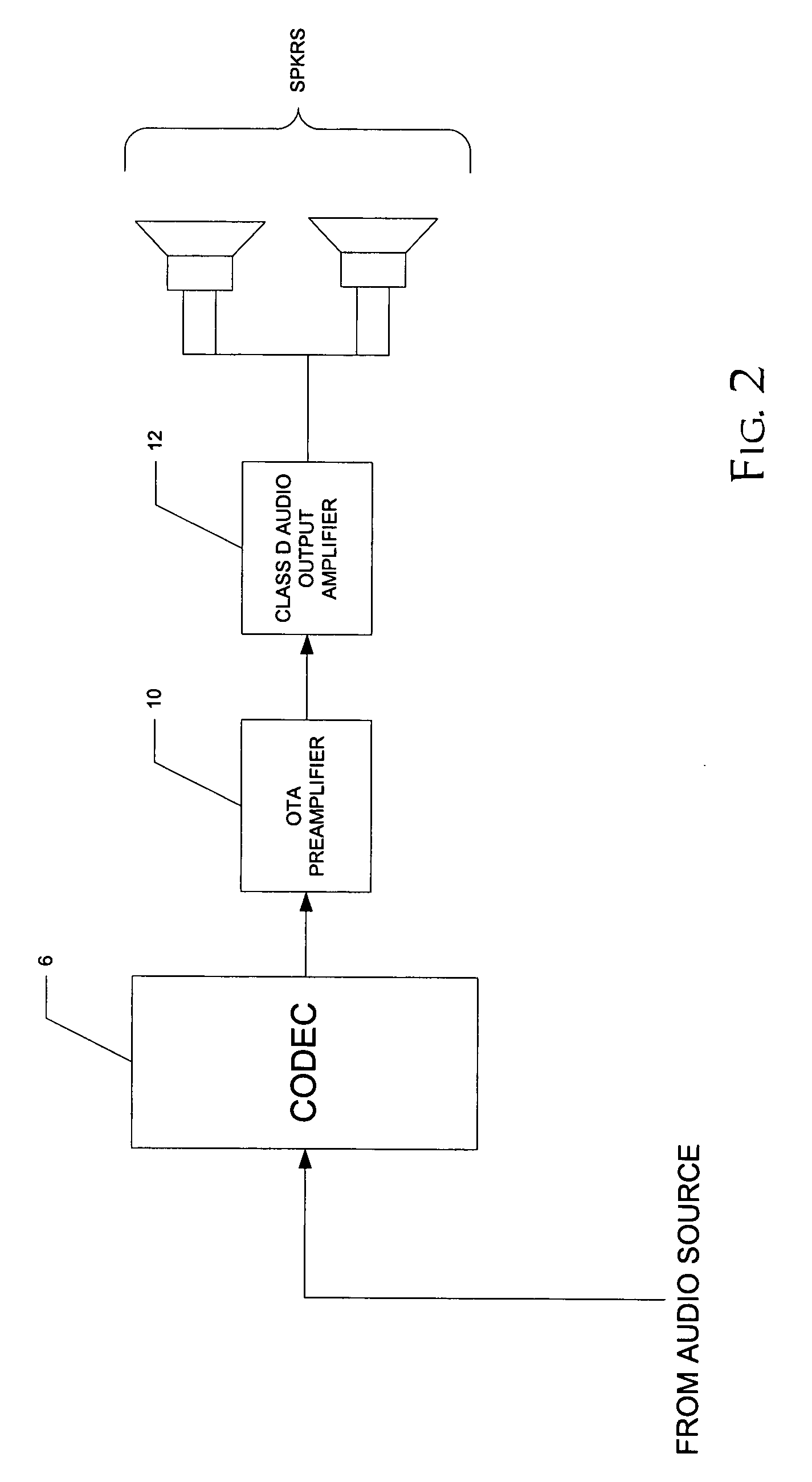
[0029]FIG. 2 illustrates an audio system into which preamplifier and audio output amplifier circuitry according to the preferred embodiment of the invention may be implemented. The audio system of FIG. 2 may represent a standalone audio system, such as an automobile, portable, or bookshelf sound system, or alternatively may be implemented within an audio-visual system, such as a television set. It is conte...


PUM


Abstract

An audio preamplifier (10) based on an operational transconductance amplifier, in combination with a class D audio output amplifier (12) is disclosed. The input signal is coupled to the preamplifier (10) through a capacitor (14) in series with a resistor (17) that sets the transconductance of the preamplifier. The preamplifier (10) includes a differential operational amplifier (20) that drives output MOS transistors (22a, 22b), which are biased by current sources (24a, 26a; 24b, 26b). Feedback from the drain nodes of the output MOS transistors (22a, 22b) to the inputs of the differential operational amplifier (20), along with the series capacitor (14) and resistor (17) input coupling, ensures minimum offset voltage and current at the output of the preamplifier (10). Common mode feedback control amplifiers (25, 29) ensure proper bias of the components into the saturation region.

Description

CROSS-REFERENCE TO RELATED APPLICATIONS[0001]Not applicable.STATEMENT REGARDING FEDERALLY SPONSORED RESEARCH OR DEVELOPMENT[0002]Not applicable.BACKGROUND OF THE INVENTION[0003]This invention is in the field of audio amplifiers, and is more specifically directed to pre-amplifier circuits for pulse-width modulated class D audio power amplifiers.[0004]As is fundamental in the art, electronic amplifier circuits are often classified in various “classes”. For example, the output drive transistors of class A amplifier circuits conduct DC current even with no audio signal, and the entire output voltage swing is of a single polarity. A class B amplifier, on the other hand, typically includes complementary output drive transistors, driving an output voltage swing including both positive and negative polarity excursions. Class B amplifiers are necessarily more efficient, because both complementary output drive transistors are never on at the same time. Class AB amplifiers maintain a small bia...

Claims


Application Information

Patent Timeline
Patent Type & Authority Patents(United States)
IPC IPC(8): H03F3/217H03F3/38H03F3/45
CPCH03F3/217H03F2200/331
Inventor LIND, RYAN E.
Owner TEXAS INSTR INC
Why Eureka
Try Eureka