Tire pressure monitoring system

a tire pressure monitoring and tire pressure technology, applied in anti-theft devices, instruments, roads, etc., can solve the problem of not being able to easily ascertain from the exterior whether the tire pressure is appropriate, and achieve the effect of facilitating the work of the operator

Inactive Publication Date: 2006-06-27
HONDA MOTOR CO LTD
View PDF15 Cites 42 Cited by
  • Summary
  • Abstract
  • Description
  • Claims
  • Application Information

AI Technical Summary

Benefits of technology

[0008]An object of this invention is therefore to overcome the foregoing problem by providing a tire pressure monitoring system that facilitates the operator's work when pumping up a tire with insufficient pressure.

Problems solved by technology

An automobile (vehicle) operator conducting a pre-driving inspection can easily check the engine oil and coolant levels visually from the exterior but has no easy way to ascertain from the exterior whether the pressure of the tires is appropriate.

Method used


Image

  • Tire pressure monitoring system
  • Tire pressure monitoring system
  • Tire pressure monitoring system

Examples


first embodiment

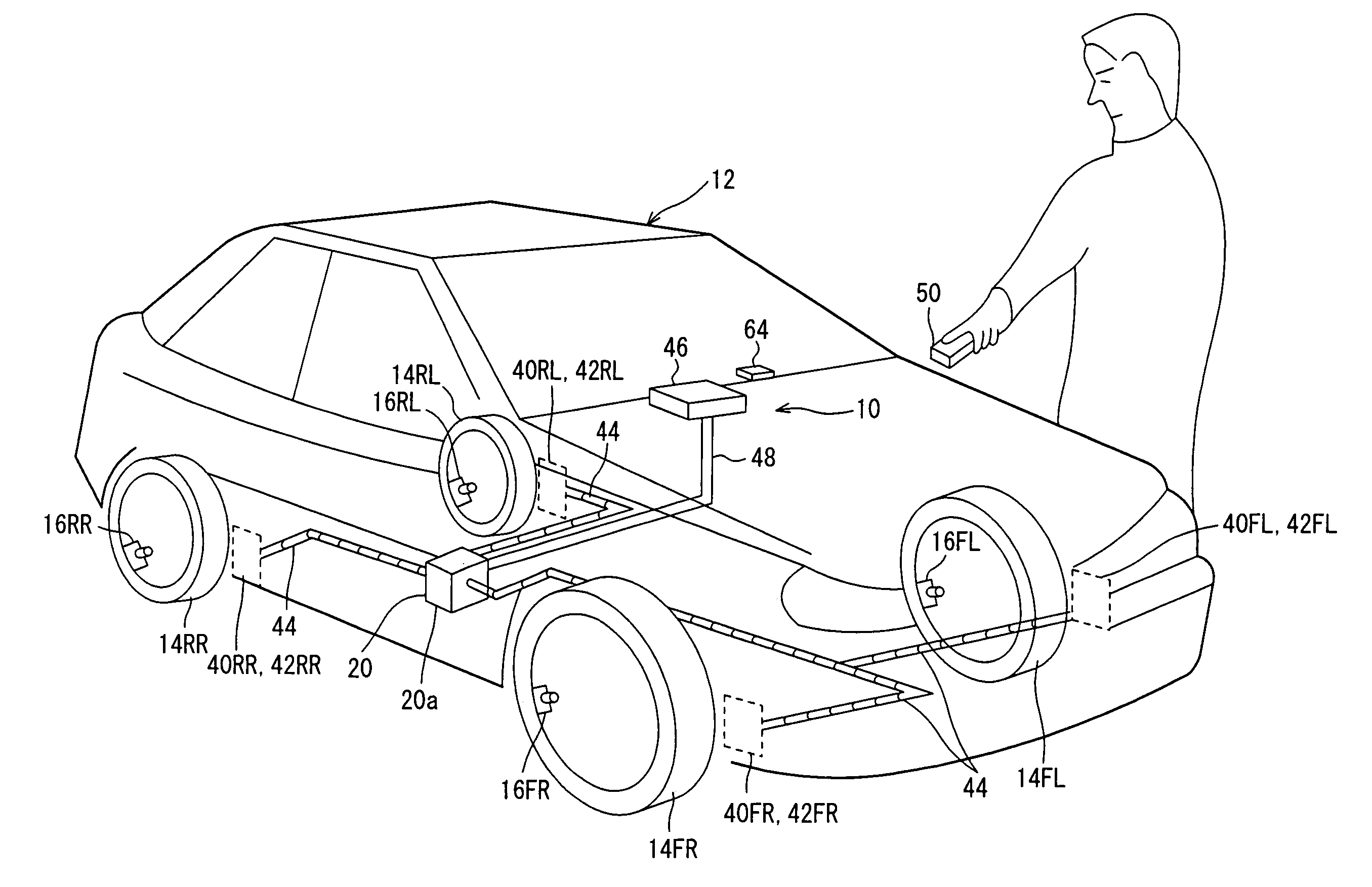
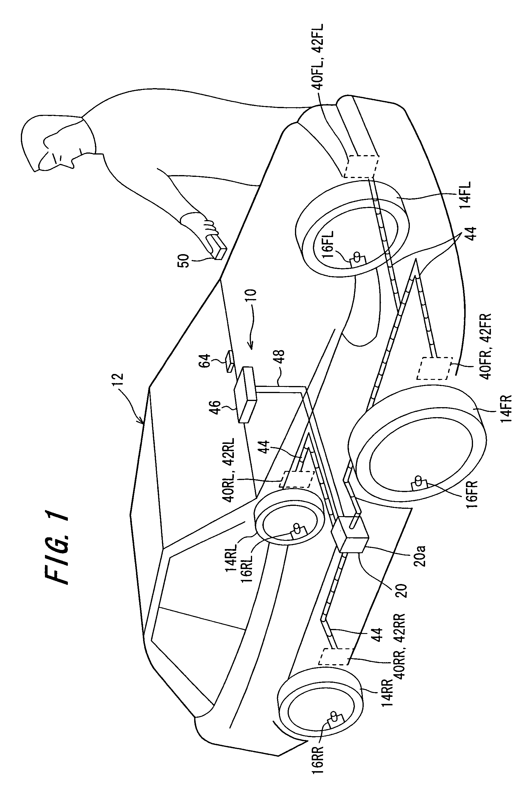
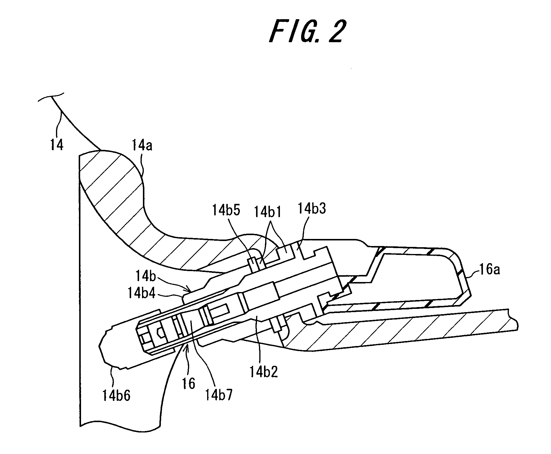
[0067]Having been described in the above, the first embodiment is arranged to have a tire pressure monitoring system comprising: a sensor unit 16 installed at each of the tires 14 mounted on a vehicle 12 and including at least a pressure sensor 24 that produces an output representing air pressure of the tire and a transmitting antenna 32 that transmits the output of the pressure sensor; a monitoring unit 20 having a receiving antenna 40 and an alarm section (the indicator 46, the warning lamp 46a, the display panel 46c), the monitoring unit receiving the output of the transmitted pressure sensor through the receiving antenna, comparing the output with a predetermined value to determine whether the tire pressure is proper, and informing a result of the determination to an operator by the alarm section; a battery 56 mounted on the vehicle and connected to the alarm section through an ignition switch 58 to supply operating power to the alarm section; and an operating switch 64 installe...

second embodiment

[0071]FIG. 8 is an explanatory block diagram similar to that of FIG. 4, but showing the operation of the tire pressure monitoring system according to this invention.

[0072]The second embodiment will be explained with regard to the points of difference from the first embodiment. In the tire pressure monitoring system according to the second embodiment, the remote keyless entry device (portable terminal device) 50 is equipped with a third receiving antenna 50a and a second indicator (alarm section) 50b. This configuration enables the foregoing determinations to be displayed on the second indicator 50b through the transmitting antennas 42 and third receiving antenna 50a in accordance with the operator's instructions.

[0073]More specifically, the remote keyless entry device 50 is equipped with the third receiving antenna 50a and the second indicator 50b, as well as a second operating button 50e, in addition to the components it requires for its basic function, namely, a built-in operating...


PUM

PropertyMeasurementUnit
temperatureaaaaaaaaaa
voltageaaaaaaaaaa
frequencyaaaaaaaaaa

Abstract

A tire pressure monitoring system having a monitoring unit that receives the output of a transmitted pressure sensor through a receiving antenna, and compares the output with a predetermined value to determine whether the tire pressure is proper, and informs a result of the determination to an operator by an indicator or alarm section connected to an onboard battery through an ignition switch. In the system, an operating switch is installed in a vehicle compartment to be operable by the operator for supplying the operating power to the indicator by connecting it to the battery, while bypassing the ignition switch. Alternatively, a portable terminal device to be carried by the operator is connected to the monitoring unit in such a manner that the monitoring unit transmits the result of the determination to the portable terminal device to inform the result of the determination to the operator by a second indicator provided at the portable terminal device. With this, the operator's work is facilitated when pumping up the tire with insufficient pressure.

Description

BACKGROUND OF THE INVENTION[0001]1. Field of the Invention[0002]This invention relates to a tire pressure monitoring system.[0003]2. Description of the Related Art[0004]An automobile (vehicle) operator conducting a pre-driving inspection can easily check the engine oil and coolant levels visually from the exterior but has no easy way to ascertain from the exterior whether the pressure of the tires is appropriate.[0005]For overcoming this inconvenience, Japanese Laid-open Patent Publication No. Sho 43(1963)-17766 teaches a tire pressure monitoring system in which a pressure-actuated switch and a sensor unit comprising a small oscillator equipped with a transmitting antenna and other components is attached to each tire, the oscillator is operated to transmit an output when the tire pressure falls to or below a predetermined value, and the transmitted output is received by a receiving antenna-equipped monitoring unit installed near the operator's seat.[0006]Moreover, well-known methods...

Claims


Application Information

Patent Timeline
Patent Type & Authority Patents(United States)
IPC IPC(8): B60C23/02G01L17/00B60C23/00B60C23/04B60R25/01B60R25/10E01C23/00G01M17/02G08B21/00
CPCB60C23/0408B60C23/0401
Inventor KOMATSU, GOROBESSHO, MAKOTO
Owner HONDA MOTOR CO LTD
Why Eureka
Try Eureka