Stereo picture recognition device and method of displaying stereo picture

a recognition device and stereo picture technology, applied in optics, instruments, electrical equipment, etc., can solve the problems of poor surround visibility, reduced transmission, and tired viewers

Inactive Publication Date: 2006-06-27
SONY CORP
View PDF12 Cites 40 Cited by
  • Summary
  • Abstract
  • Description
  • Claims
  • Application Information

AI Technical Summary

Benefits of technology

[0011]It is therefore an object of the present invention to provide a stereo picture recognition device and a method of display...

Problems solved by technology

This causes the viewer to sense flicker in a surrounding landscape, especially when the external light is bright, to thereby make the viewer ...

Method used


Image

  • Stereo picture recognition device and method of displaying stereo picture
  • Stereo picture recognition device and method of displaying stereo picture
  • Stereo picture recognition device and method of displaying stereo picture

Examples


Embodiment Construction

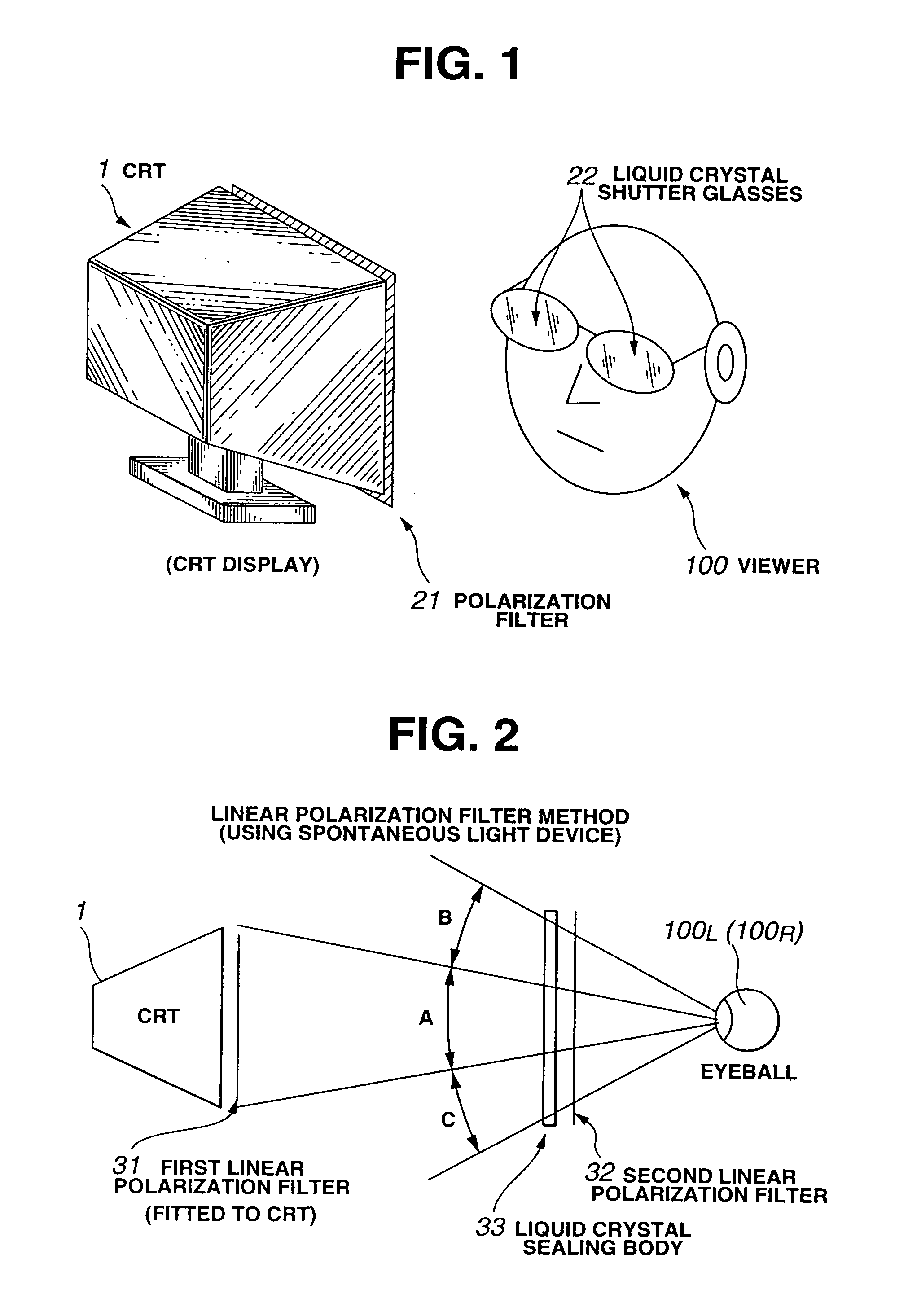
[0030]As is seen in FIG. 1, there is provided an overview of a stereo picture recognition device using liquid crystal shutter glasses, under the present invention.

[0031]There is provided a CRT 1 (a stereo picture display), a polarization filter 21 (polarization converting means), and a pair of liquid crystal shutter glasses 22 for viewing a screen (picture plane) of the CRT 1. The CRT 1 in FIG. 1 is substantially the same as the CRT 1 according to the earlier technology in FIG. 8. The liquid crystal shutter glasses 22 in FIG. 1 are different from the liquid crystal shutter glasses 2 according to the earlier technology in FIG. 8. The video signal is supplied to the CRT 1 substantially in the same manner as shown in FIG. 9(a) (earlier technology). Moreover, electric signals for transmission and shutoff show substantially the same period as those shown in FIG. 9(b) and FIG. 9(c) (earlier technology).

[0032]With this constitution, it is only in the display area of the CRT 1 that the liqu...


PUM


Abstract

A stereo picture recognition device has a time-sharing picture display shutter disposed between a display surface of a display device and a viewer. The time-sharing picture display shutter has a function of shutting off only an area covered by a viewing angle which corresponds to a display area of the display device.

Description

RELATED APPLICATION DATA[0001]The present application claims priority to Japanese Application No. P2001-185635 filed Jun. 1, 2001, which application is incorporated herein by reference to the extent permitted by law.BACKGROUND OF THE INVENTION[0002]The present invention relates to a stereo picture recognition device and a method of displaying the stereo picture for recognizing, without sensing flicker, the stereo picture which is displayed by a time-sharing system.[0003]As is seen in FIG. 8, there is provided a stereo picture recognition device (stereo picture display system) using a pair of liquid crystal shutter glasses, according to an earlier technology. In FIG. 8, there are shown a cathode ray tube 1 (hereinafter referred to as “CRT 1”) used as a stereo display device, and a pair of liquid crystal shutter glasses 2. A viewer facing the CRT 1 and wearing the liquid crystal shutter glasses 2 allows a right liquid crystal shutter 2R to be disposed in front of a right eye 100R of t...

Claims


Application Information

Patent Timeline
IPC IPC(8): G09G5/00G02B27/22G02F1/1335H04N13/04G02F1/13G02B30/25H04N13/00
CPCG02B27/2264H04N13/0422H04N13/0497H04N13/0438H04N13/0459H04N13/0048H04N13/0434H04N13/0427G02B30/24H04N13/161H04N13/324H04N13/337H04N13/341H04N13/363H04N13/365H04N13/398
Inventor SATO, SEIJIKAWAMURA, AKIRA
Owner SONY CORP
Why Eureka
Try Eureka