
Rearview monitoring apparatus for vehicle

a technology for rearview monitoring and vehicle, which is applied in the direction of static indicating devices, television systems, instruments, etc., can solve the problems of inability to understand the positioning relationship between the obstacles around the vehicle and the spare tire, the inability to open the tailgate of the vehicle, and the inability to acknowledge the positioning relationship sufficiently

Inactive Publication Date: 2006-06-27
HONDA MOTOR CO LTD
View PDF9 Cites 133 Cited by
  • Summary
  • Abstract
  • Description
  • Claims
  • Application Information

AI Technical Summary

Benefits of technology

The present invention provides a rearview monitoring apparatus for a vehicle that can display a rearview image and information about the vehicle's protruding region, which can collide with obstacles around the vehicle. The apparatus includes a vehicle index storing device that stores a vehicle index representing the vehicle's protruding region and a superposed image displaying device that can display the vehicle's rear reference position and the vehicle's protruding region in the form of an index. This allows the occupants in the vehicle to park the vehicle close to obstacles around the vehicle without colliding with them. The apparatus can also provide more detailed information about the space occupied by the vehicle's protruding region and can help the occupants avoid collisions with obstacles.

Problems solved by technology

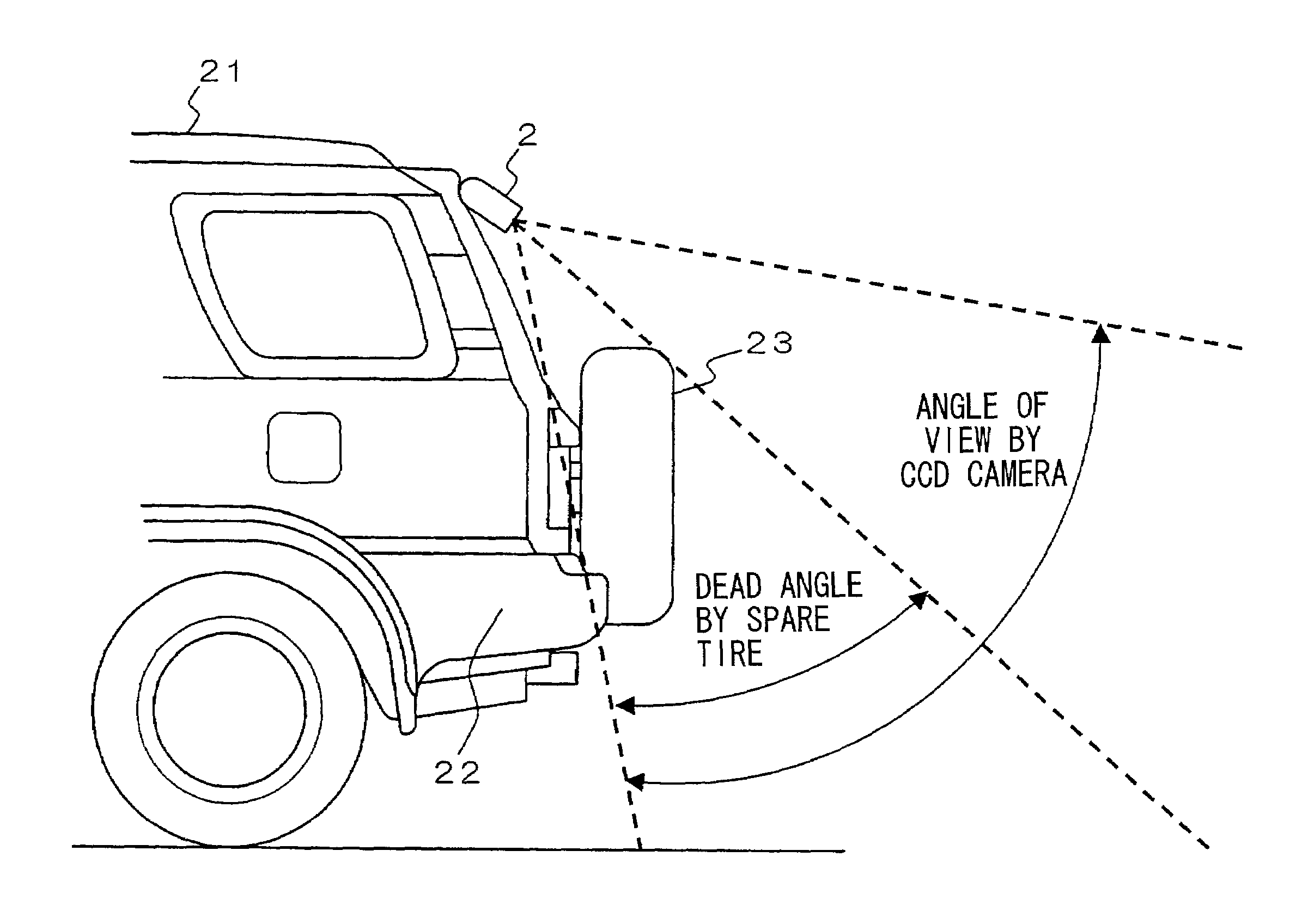
However, it was not possible to acknowledge sufficiently the positioning relationship between the vehicle and the obstacle around the vehicle when a protruding object such as a spare tire is attached on the rear end of the vehicle, even though it was possible to acknowledge the positioning relationship between the vehicle and the obstacle around the vehicle by displaying the rear end part of the vehicle in the rearview image of the conventional apparatus.
Thus, there was a problem in that it was impossible to understand the positioning relationship of the obstacles around the vehicle and the spare tire 23 according to the rearview image sufficiently.
Therefore, there was sometimes a problem in that the tailgate of the vehicle could not be opened after the vehicle was parked.
Also, on the other hand, there were problems as follows.

Method used


Image

  • Rearview monitoring apparatus for vehicle
  • Rearview monitoring apparatus for vehicle
  • Rearview monitoring apparatus for vehicle

Examples


first example

[0064]First, a case is explained in which the rearview monitoring apparatus for a vehicle displays a superposed image of a vehicle's protruding region which protrudes in a rear direction over a rear reference position of the vehicle in a corresponding position of the vehicle's protruding region in the rearview image as a vehicle index which is indicated by lines according to a first example of the present invention.

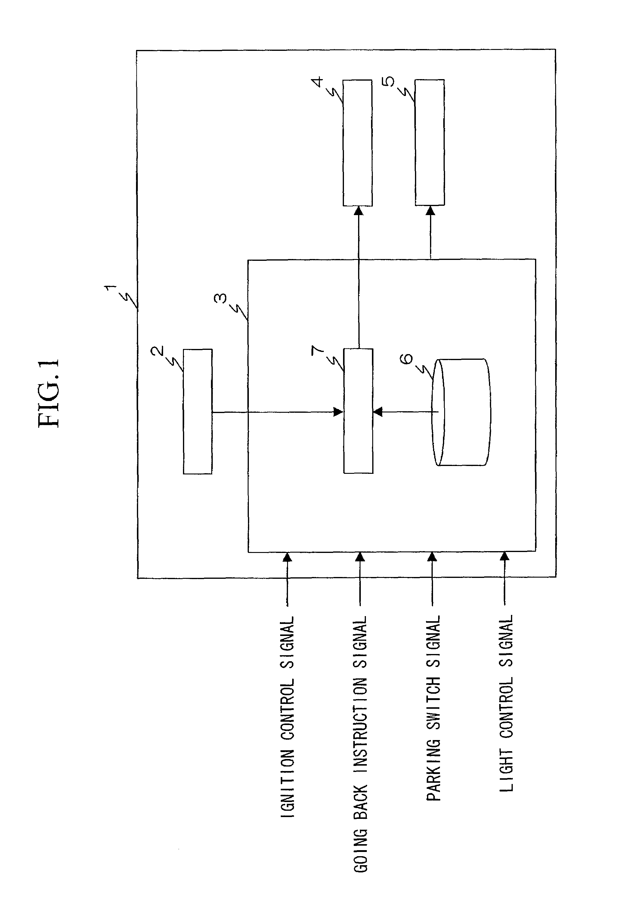
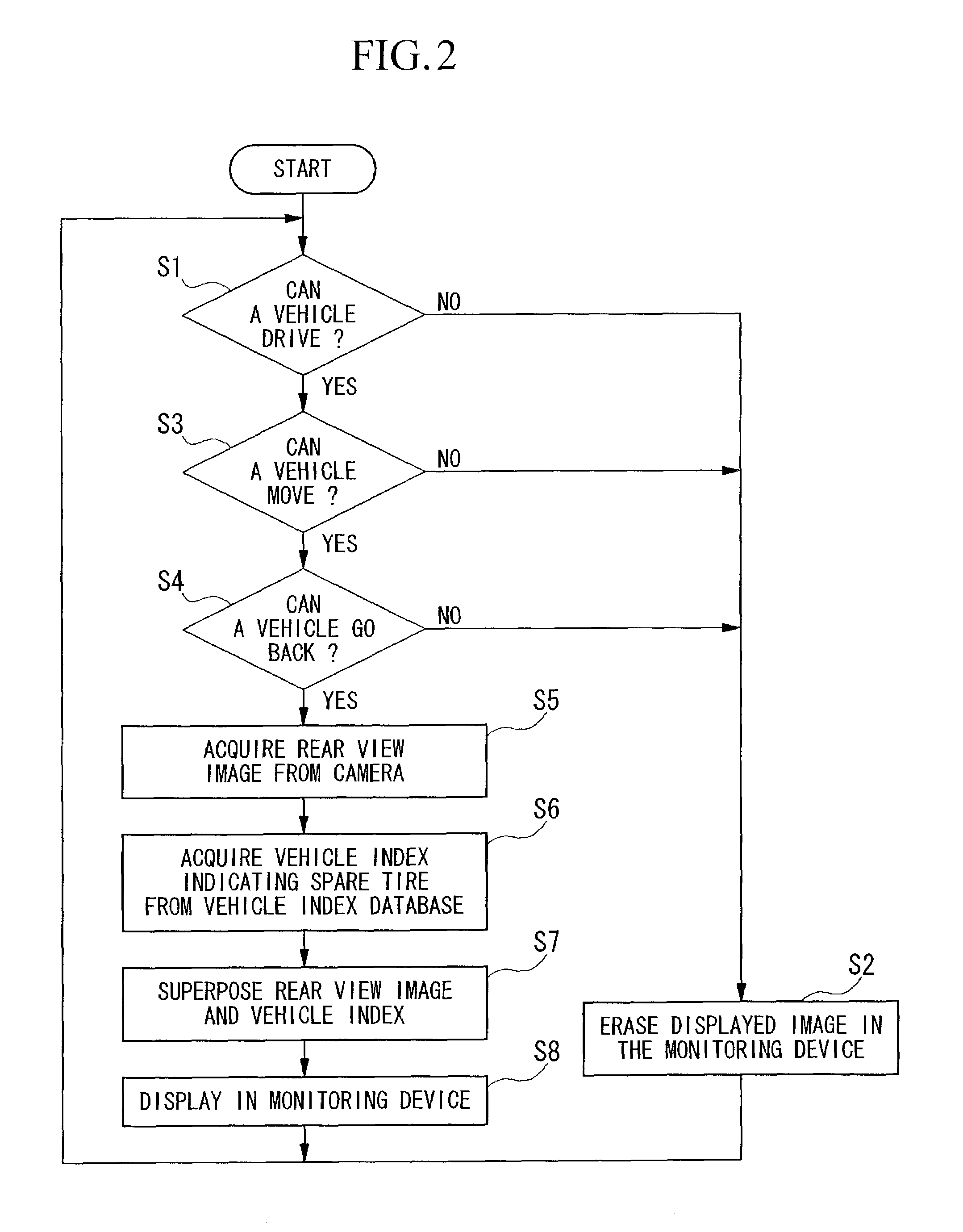
[0065]FIG. 2 is a flow chart for showing a movement of the rearview monitoring apparatus 1 for a vehicle for displaying a rearview image in a monitoring device 4. First, a controlling unit 3 in the rearview monitoring apparatus 1 for vehicle determines whether or not the engine has started by the ignition signal and the vehicle 21 can be driven (Step S1).

[0066]In Step S1, when an engine has not started and a vehicle is not ready to be driven (NO in Step 1), a superposed image displaying device 7 in a control section 3 erases an image which is displayed on a monitoring dev...

second example

[0078]Next, as a second example, a case in which the rearview monitoring apparatus for a vehicle displays a superposed image of the vehicle's protruding region which protrudes in a rear direction over the rear reference position of the vehicle as a vehicle index which is indicated by a picture such as a projected shadow on the road surface in a position corresponding to the vehicle's protruding region in the rearview image is explained.

[0079]Here, in this example, an operation of the rearview monitoring apparatus 1 for a vehicle for displaying the rearview image in the monitoring device 4 is the same as the case of the first example of the present invention. Also, the vehicle's protruding region is explained with reference to a spare tire 23 which is attached to the rear end of the vehicle 21.

[0080]FIG. 5 is a view for showing an example of displayed rearview image according to the second example of the present invention. In FIG. 5, a distance index 52 which indicates 1 m of distanc...

third example

[0091]A third example of the present invention is explained with reference to a case in which the rearview monitoring apparatus for a vehicle displays a superposed image of the rear door as a vehicle index indicated by a line which is opened in a rear direction over the rear reference position of the vehicle in a position corresponding to the opened rear door in the rearview image.

[0092]Steps 1 through 5 in a flow chart shown in FIG. 8 show the operation of the rearview monitoring apparatus 1 for a vehicle for displaying the rearview image in the monitoring device 4 are the same as the first example; thus the explanation thereof is omitted.

[0093]The superposed image displaying device 7 acquires a vehicle index which indicates a tailgate 123 from the vehicle index database 6 (Step S16).

[0094]After that, the superposed image displaying device 7 superposes the vehicle index which indicates a tailgate 123 in the rearview image (Step S17), and displays the superposed image in the monitor...


PUM


Abstract

A CCD camera takes rearview images of a vehicle so as to input them into a superposing image displaying device, and a vehicle index database stores a vehicle index indicating a vehicles's protruding region such as a spare tire for displaying the protruding region over a rear end of a rear reference position such as a bumper of the vehicle in the rearview image. A superposed image displaying device superposes the vehicle index stored in the vehicle index database and the rearview image taken by the CCD camera so as to provide a monitoring device. Thus, a rearview monitoring apparatus for a vehicle for displaying the rearview image of the vehicle and information of the protruding region for occupants in the vehicle can be provided.

Description

BACKGROUND OF THE INVENTION[0001]1. Field of the Invention[0002]The present invention relates to a rearview monitoring apparatus for a vehicle which is carried on the vehicle and displays rearview images taken by a camera device to occupants in the vehicle.[0003]2. Description of Related Art[0004]Conventionally, a rearview monitoring apparatus for a vehicle for taking rearview images of the vehicle by a camera and displaying the rearview images as supplementary information for a driver by a monitoring device which is located near a driver's seat is known.[0005]As such an apparatus, for example, an apparatus which comprises a camera for taking a rearview image of the vehicle and a superposing device which displays a vehicle width line indicating the width of the vehicle and a distance line indicating the distance of an obstacle from the vehicle in an image taken by the camera is disclosed in Japanese Unexamined Patent Application, First Publication No. Hei 10-151991.[0006]This appara...

Claims


Application Information

Patent Timeline
Patent Type & Authority Patents(United States)
IPC IPC(8): G09G5/00B60R1/00H04N7/18
CPCB60R1/00H04N7/183B60R2300/301B60R2300/806B60R2300/8093B60R2300/305B60R1/26
Inventor SATOH, TATSUYAHAYASHI, NORIYUKI
Owner HONDA MOTOR CO LTD
Learn More