Air vehicle with a slip protecting and gas sealing composite floor

a composite floor and air vehicle technology, applied in the direction of transportation and packaging, synthetic resin layered products, chemical instruments and processes, etc., can solve the problems of high cost, complex and expensive production of current floor structures of transport aircraft, and the need for expensive and laborious floor treatment, so as to reduce the vibration and sound levels inside the fuselage of inventive air vehicles

Inactive Publication Date: 2015-09-22
AIRBUS HELICOPTERS DEUT GMBH
View PDF9 Cites 0 Cited by
  • Summary
  • Abstract
  • Description
  • Claims
  • Application Information

AI Technical Summary

Benefits of technology

[0048]According to the invention an air vehicle with a slip protecting and gas sealing composite floor or a slip protecting and gas sealing composite floor panel inside a fuselage is provided, particularly a helicopter with a slip protecting and gas sealing composite floor inside a fuselage. Said slip protecting and gas sealing composite floor is built up of a profiled elastomer layer provided at its bottom side with a cross-linking agent, a further component of n-layers and partially thermosetting resin covered by said profiled elastomer layer, a honey comb layer and a further component of lower n-layers and partially thermosetting resin. Said honey comb layer is sandwiched between said n-layers and said lower n-layers. The inventive air vehicle is provided with an efficient slip protecting and gas sealing composite floor inside a fuselage due to the optimized kind of material used. The elasticity of the surface as well as the structuring of the surface and roughness of the floor allows safe interaction of shoes and boots with different kinds of soles, as well as metal / plastic / wooden boxes / containers with the aircraft floor. The slip protecting and gas sealing composite floor of the invention allows cure of the complete floor or of the floor panels for an inventive air vehicle in one production step by enclosing a sequence of layers into a curing form to thermally treat them. This thermal treatment starts a vulcanization process for the elastomer layer(s), a hardening process for the resin and at the same time a chemical reaction between resin and elastomer which creates an indestructible combination of the resin and the elastomer. During vulcanization, the top layer elastomer can be shaped already in such a way, that its surface structure is appropriate to provide the necessary escape space for any liquids or greasy pollutants, such as water, snow, mud etc., and thus providing the efficient slip protecting and gas sealing composite floor. The elastomer layer as a top layer provides the necessary visco-elasticity for increasing the contact area between the floor and the material / shoe soles on top of the slip protecting and gas sealing composite floor with the above mentioned efficient friction level. At the same time, by using the elastomer in the proposed way, the slip protecting and gas sealing composite floor achieves the required gas isolation properties.
[0055]According to a further preferred embodiment of the invention the vibration and sound levels inside the fuselage of the inventive air vehicle can be reduced by using several layers of elastomers which are intermixed into the sequence of n-layers and lower n-layers for the slip protecting and gas sealing composite floor.
[0056]According to a further preferred embodiment of the invention several layers of fiber tissue with an E-Module higher than 100 GPa, a tear strength of more than 2.5 GPa, and a breaking elongation of more than 2%, e.g. Aramid or Zenon, are each embedded into elastomer layers which are intermixed into the sequence of n-layers and lower n-layers to make the slip protecting and gas sealing composite floor crashworthy and ballistically secure.

Problems solved by technology

Current floor structures for transport aircrafts are either complex and expensive for production or their weight is a significant limitation.
If there is a need for slip protection or for sealing of a fuselage against gases by means of said floor structures expensive and laborious treatment of the floor is needed.
Disadvantages of Resin Treated Material on Top:resin treated material normally is very sensitive against any kind of impact during a loading / unloading process.
The resin can chip of easily and therefore floor panels made of resin treated material normally have a short lifetime,the shaping of the surface in order to satisfy the requirements for slip protection above is not easy to realize,the resin treated material is not visco-elastic and provides no or very low deformation frictionthe floor panels need to be painted in an additional process step andthe sealing against gases is independent of slip protection and requires additional efforts.
Disadvantages of Metal on Top:if the metal is aluminum, the shaping of the surface in order to satisfy the above mentioned requirements for slip protection requires casting or milling techniques.
Said techniques are very time consuming and expensive,if the metal is iron, the shaping can be done easily but the resulting weight of the floor is fairly high,the material is not visco-elastic and provides no or very low deformation friction,if fiber material is involved, the composite structures need to be painted in an additional process step, andthe sealing against gases is independent of slip protection and requires additional efforts.
Disadvantages of Glued Slip Protection Foils:if fiber material is involved, the glued slip protection foils of the floor panels need to be painted in an additional process step,the glued slip protection foils require additional and labour-intensive production steps,the glued slip protection foils need to be produced in a separate production process, andthe sealing against gases is independent from slip protection and requires additional effort.
Disadvantages of Rolled on Protection Material:if fiber material is involved, the rolled on protection material of the floor panels need to be painted in an additional process step,rolled on protection material requires additional and labour-intensive production steps, andthe sealing against gases is independent from slip protection and requires additional efforts.

Method used


Image

  • Air vehicle with a slip protecting and gas sealing composite floor
  • Air vehicle with a slip protecting and gas sealing composite floor
  • Air vehicle with a slip protecting and gas sealing composite floor

Examples


Embodiment Construction

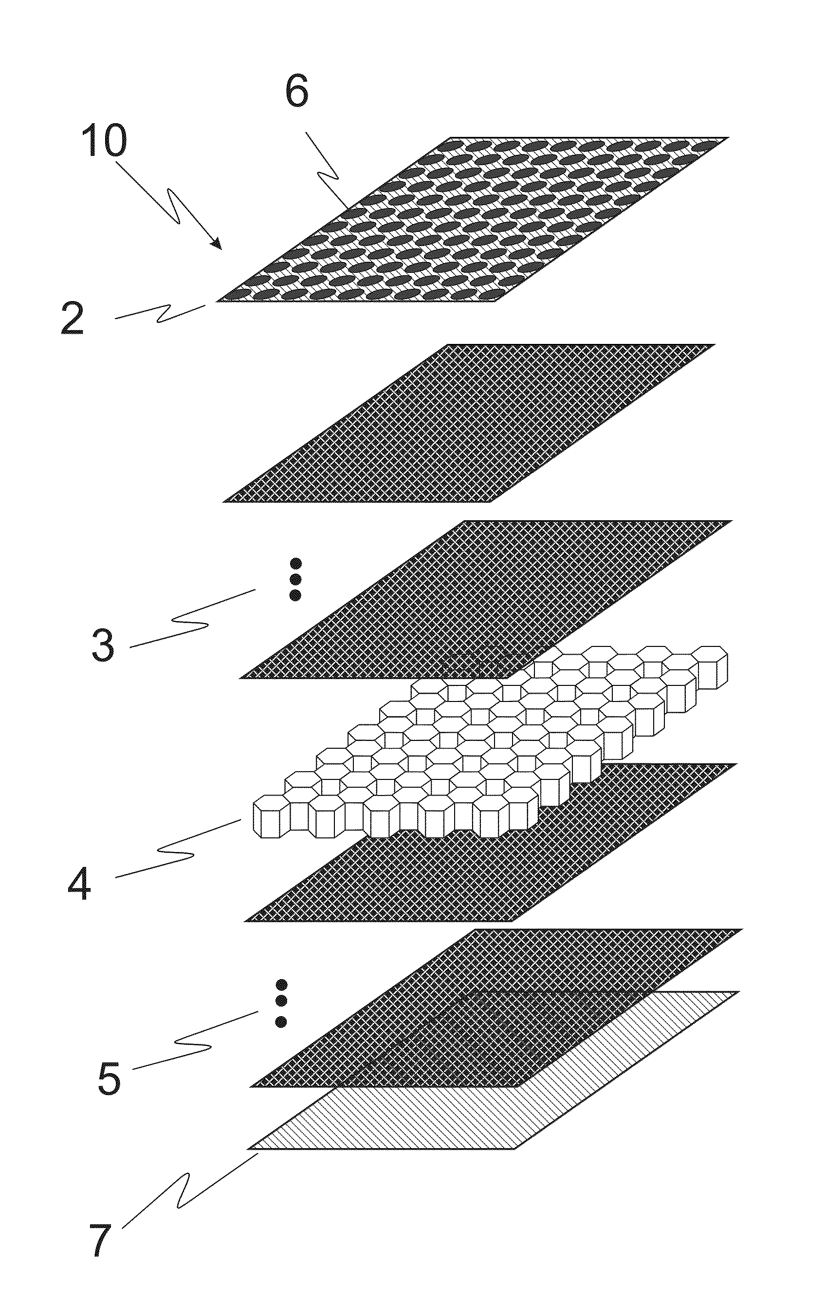
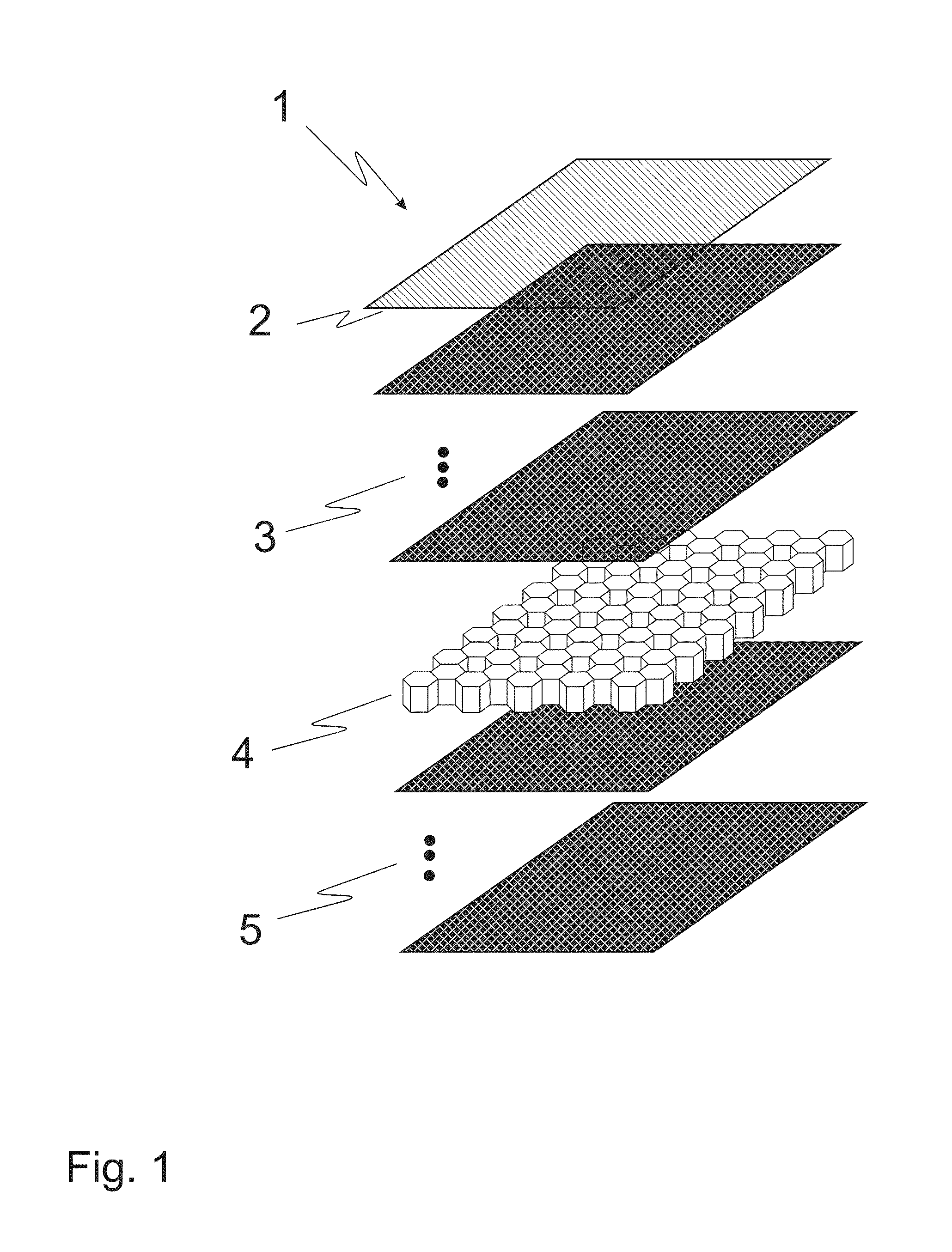
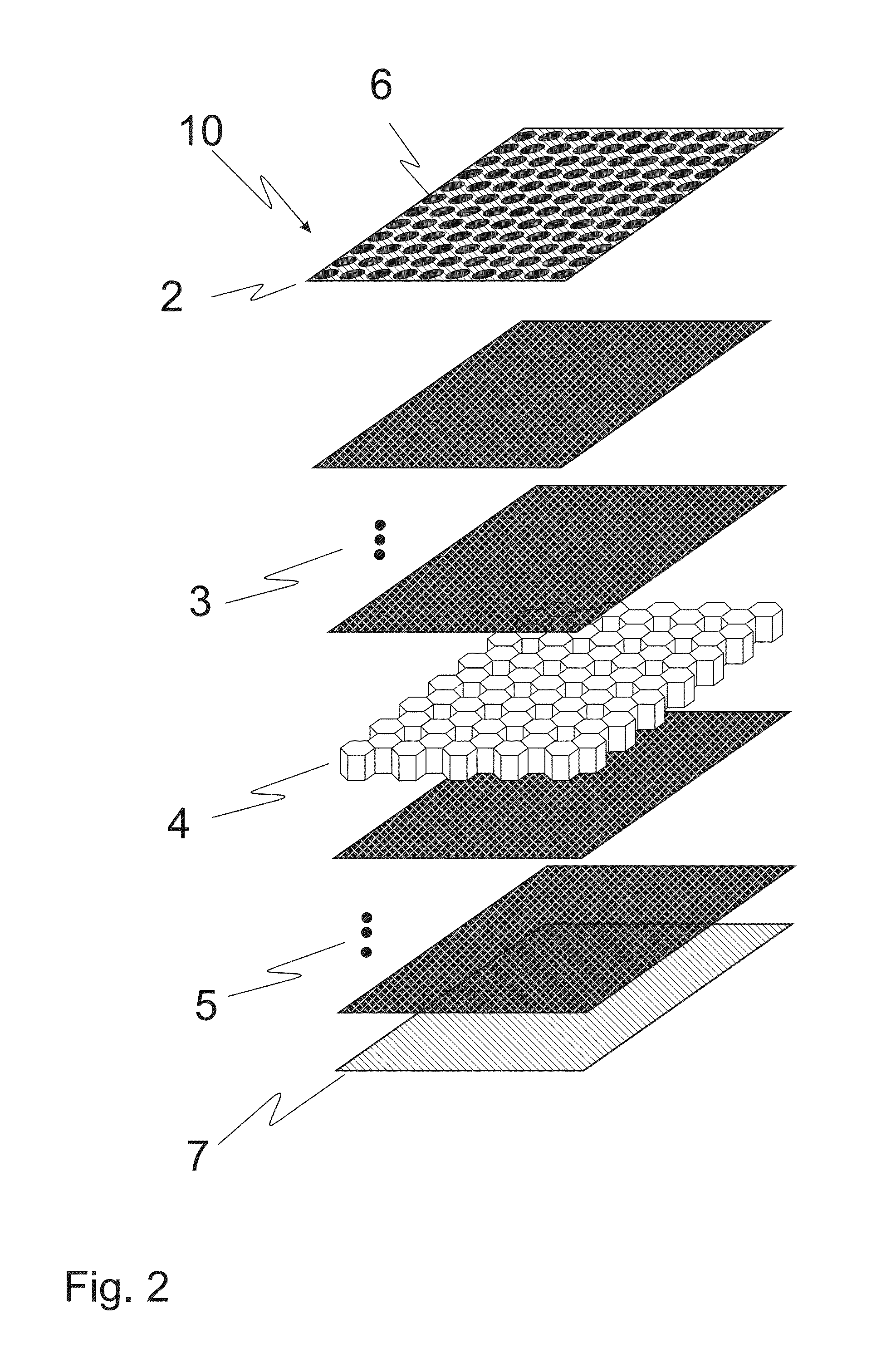
[0062]According to FIG. 1 a slip protecting and gas sealing composite floor 1 for an air vehicle (not shown) is made of an upper profiled elastomer layer 2 provided at its bottom side with at least one cross-linking agent.

[0063]The upper profiled elastomer layer 2 covers one or n-layers 3 made of a fabric, elastomer or sheet metal / metal foils and at least partially thermosetting resin. The one or n-layers 3 of fabric, elastomer or sheet are made from metal, metal fibre, glass fibre, nylon fibre, carbon fibre, aramide or poly(p-phenylene-2,6-benzobisoxazole) fibre, etc. according to static or protective needs. Said one or n-layers 3 cover a honeycomb structure 4.

[0064]One or a plurality of lower layers 5, namely lower n-layers 5, are made of the fabric, elastomer or sheet metal / metal foils and the at least partially thermosetting resin. The honeycomb structure 4 is sandwiched between the one or plurality of layers 3 and the one or plurality of lower layers 5. A bottom side of the one...


PUM

PropertyMeasurementUnit
breaking elongationaaaaaaaaaa
tear strengthaaaaaaaaaa

Abstract

An air vehicle, particularly a helicopter, includes a slip protecting and gas sealing composite floor inside a fuselage. The slip protecting and gas sealing composite floor is built up of a profiled elastomer layer provided at its bottom side with a cross-linking agent, n-layers of a further component or a variety of different components and partially thermosetting resin covered by a profiled elastomer layer, a honey comb layer and lower n-layers of the further component or variety of different components and partially thermosetting resin, the honey comb layer being sandwiched between the n-layers and the lower n-layers.

Description

CROSS REFERENCE TO RELATED APPLICATIONS[0001]This application claims priority to European patent application No. 11 400057.3 filed Nov. 22, 2011, the disclosure of which is incorporated in its entirety by reference herein.BACKGROUND OF THE INVENTION[0002](1) Field of the Invention[0003]The invention relates to an air vehicle with a slip protecting and gas sealing composite floor inside a fuselage, the composite floor including at least one profiled elastomer layer provided at its bottom side with a cross-linking agent, one or n-layers of a further component or a variety of further components and partially thermosetting resin covered by the profiled elastomer layer, a honey comb layer and one lower layer or lower n-layers of the further component or a variety of further components and partially thermosetting resin, the honey comb layer being sandwiched between the n-layers and the lower n-layers.[0004](2) Description of Related Art[0005]Current floor structures for transport aircraft...

Claims


Application Information

Patent Timeline
Patent Type & Authority Patents(United States)
IPC IPC(8): B64C1/18B32B3/30B32B3/12B32B15/08B32B27/12
CPCB64C1/18B32B3/12B32B3/30B32B15/08B32B27/12B32B2250/40B32B2274/00B32B2307/7242B32B2307/744B32B2605/003B32B2605/18
Inventor HEBENSPERGER, MICHAELKREITMAIR-STECK, WOLFGANG
Owner AIRBUS HELICOPTERS DEUT GMBH
Why Eureka
Try Eureka