Flexible shaft arrangement

a flexible shaft and shaft arrangement technology, applied in the field of mechanical engineering, can solve the problems of affecting the affecting the operation of the shaft, and corresponding unpleasant noise, and achieve the effect of ensuring the minimum service life of the shaft arrangement, high speed, and low friction

Active Publication Date: 2015-01-13
ECP ENTWICKLUNGSGMBH
View PDF249 Cites 31 Cited by
  • Summary
  • Abstract
  • Description
  • Claims
  • Application Information

AI Technical Summary

Benefits of technology

[0007]It is the underlying object of the present invention with respect to the prior art to provide a shaft arrangement which allows an operation of the shaft at high speeds with low friction and in so doing ensures that a minimum service life of the shaft arrangement can be

Problems solved by technology

Different problems result in the operation of such shafts, in particular as a consequence of the vibration behavior.
Small asymmetries at certain points of a shaft arrangement and/or a

Method used


Image

  • Flexible shaft arrangement
  • Flexible shaft arrangement
  • Flexible shaft arrangement

Examples


Embodiment Construction

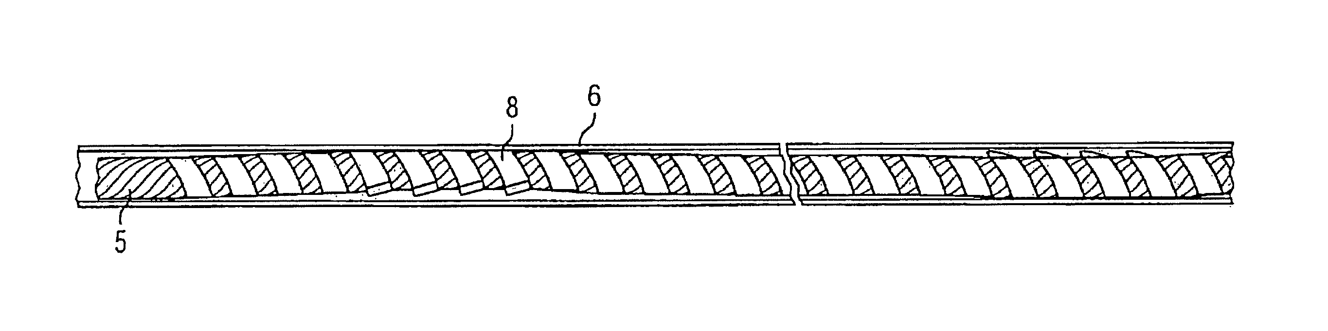
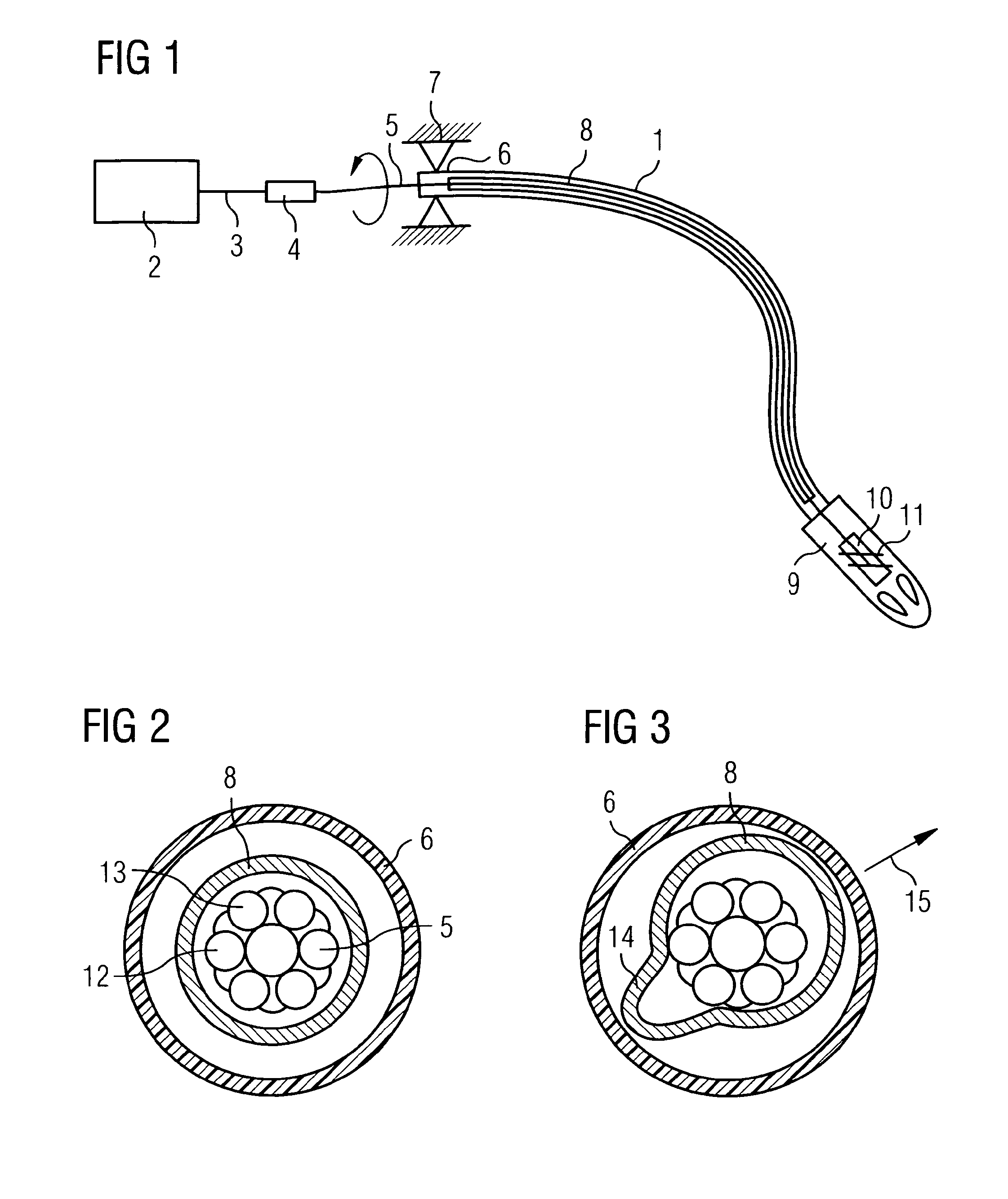
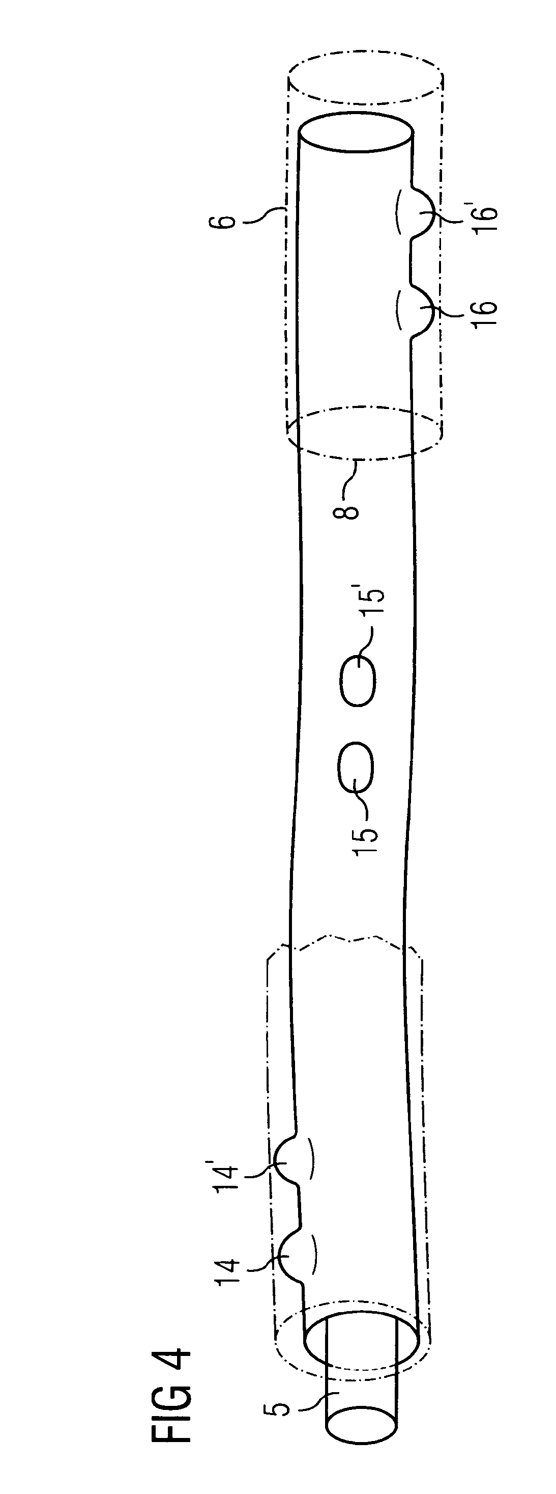
[0037]FIG. 1 shows the shaft arrangement 1 in a schematic view with a motor drive which has an electric motor 2 as well as a motor shaft 3 and a coupling 4 by means of which the flexible shaft 5 is rotationally fixedly coupled to the motor 2. In addition, a jacket 6 of the shaft arrangement is shown which is fixed in the holder 7 at the motor side. A sleeve 8 which surrounds the shaft 5 is shown in the interior of the jacket.

[0038]A pump 9 having a pump rotor 10 which has impeller blades 11 is shown on the output side of the shaft arrangement. Such a pump can serve in medical engineering in the microinvasive sector, for example, for conveying blood in a blood vessel and forms a very fast-rotating axial flow pump.

[0039]The shaft arrangement in accordance with the invention solves the problem that the very fast-rotating shaft 5, i.e. rotating at more than ten thousand revolutions per minute, can be prone to knocking movements which can result in disturbing noise development and in som...


PUM

PropertyMeasurementUnit
Lengthaaaaaaaaaa
Flexibilityaaaaaaaaaa

Abstract

A flexible shaft arrangement is provided having a ductile shaft, a sleeve which surrounds the shaft as well as a jacket which surrounds the shaft and the sleeve. The sleeve extends within the jacket at least sectionally in arcuate form and thus produces a contact of the shaft at the inner contour of the sleeve point-wise. Vibrations or knocks of the shaft are thus effectively damped.

Description

BACKGROUND OF THE INVENTION[0001]The invention is in the field of mechanical engineering, in particular mechanics, and relates to the transfer of torques and movements via flexible shafts. Flexible shaft drives are known from different fields of the art, with them varying greatly with respect to the torques to be transferred and the speeds. Shaft arrangements are, for example, known from the field of flexibly usable machine tools which run at relatively low speeds and should transfer high torques, whereas shafts are known from dental engineering which rotate at extremely high speeds and transfer lower torques.[0002]Different problems result in the operation of such shafts, in particular as a consequence of the vibration behavior. Small asymmetries at certain points of a shaft arrangement and / or at certain speeds can result in knocking movements with corresponding unpleasant noise developments and in mechanically high strains due to friction between the shaft and its guidance.[0003]D...

Claims


Application Information

Patent Timeline
IPC IPC(8): F16C1/06B23P17/00A61M1/10A61M1/12F16C41/00
CPCF16C1/06A61M1/125F16C41/008A61M1/101F16C1/26Y10T74/20456Y10T29/49A61M60/414A61M60/148A61M60/237A61M60/13
Inventor LIEBING, REINER
Owner ECP ENTWICKLUNGSGMBH
Why Eureka
Try Eureka