Magnetic core, magnetic component and design method of magnetic core

a technology of magnetic core and design method, which is applied in the direction of magnetic core manufacturing, transformer/react mounting/support/suspension, transformer/inductance magnetic core, etc., can solve the problem of difficult to heighten the flange portion occupied-area ratio with respect to the mounting region, and become ineffectively using these excess spaces as spaces, etc. problem, to achieve the effect of using excess spa

Active Publication Date: 2015-06-23
SUMIDA CORP
View PDF10 Cites 1 Cited by
  • Summary
  • Abstract
  • Description
  • Claims
  • Application Information

AI Technical Summary

Benefits of technology

[0016]According to a magnetic core having such a characterized structure, it becomes possible, by adjusting the shape of the contour line OL1 of the cross-section P of the flange portion corresponding to the shape of the abovementioned first circumscribed rectangle, to secure a useful excess space within the mounting region, in which a terminal or the like is arranged while heightening the flange portion occupation-area ratio in case of setting the inside of the first circumscribed rectangle to be the mounting region.
[0044]In addition, according to a design method of a magnetic core relating to the present invention, it becomes possible to design a magnetic core in which there can be secured a necessary space for placing the flange portion and a useful excess space even within a narrow mounting region.

Problems solved by technology

However, when the mounting region is narrowed and decreased, the areas of the respective excess spaces become small in response thereto and therefore, there is a fear that it becomes impossible to effectively utilize these excess spaces as the spaces for arranging extended portions of the terminals or the like.
Also, since the flange portion is formed to be disk-like, it is also difficult to heighten the flange portion occupation-area ratio with respect to the mounting region.

Method used


Image

  • Magnetic core, magnetic component and design method of magnetic core
  • Magnetic core, magnetic component and design method of magnetic core
  • Magnetic core, magnetic component and design method of magnetic core

Examples


Embodiment Construction

[0060]Hereinafter, there will be explained exemplified embodiments of a magnetic core, a magnetic component and a design method of the magnetic core relating to the present invention in detail while referring to the abovementioned drawings.

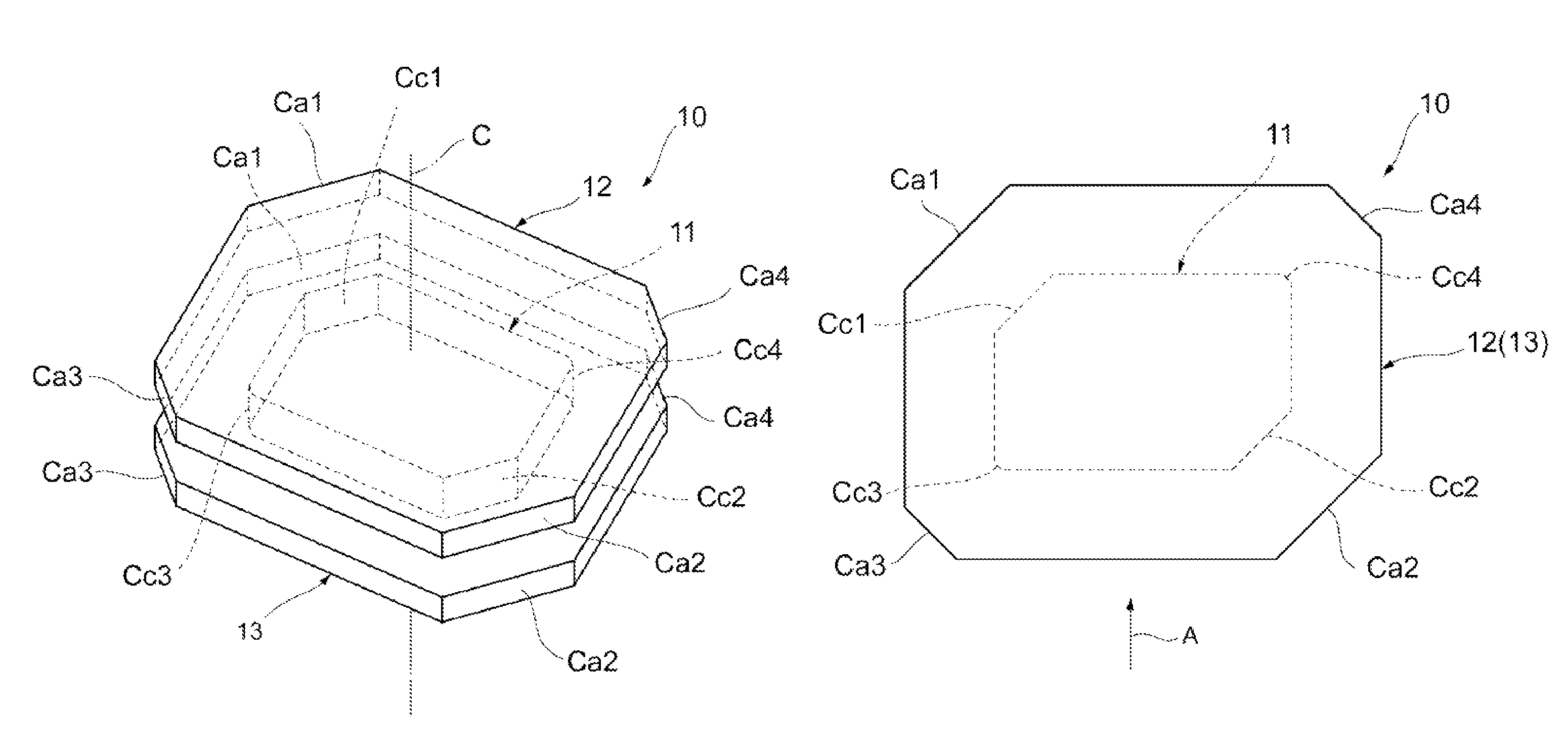
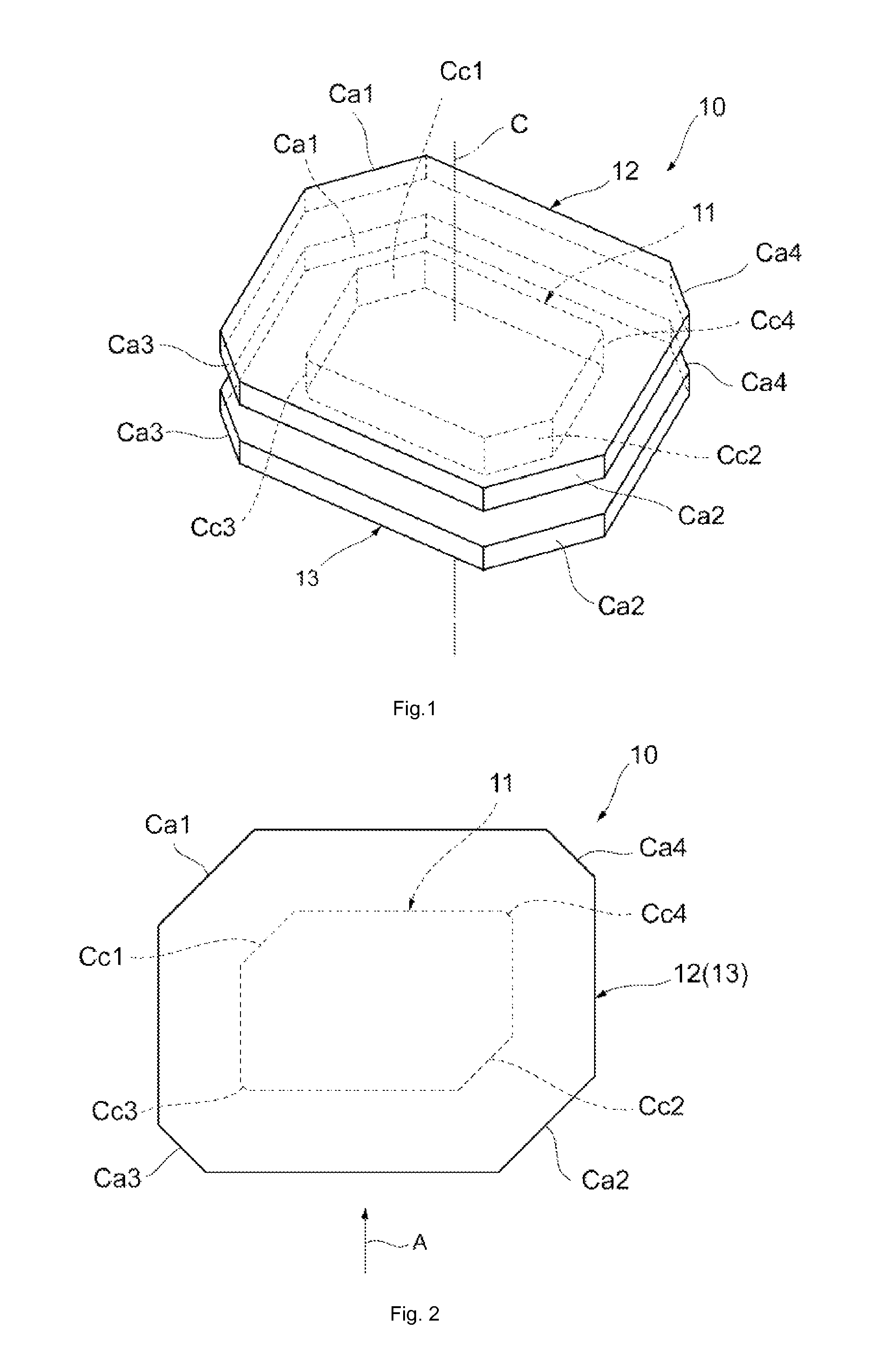
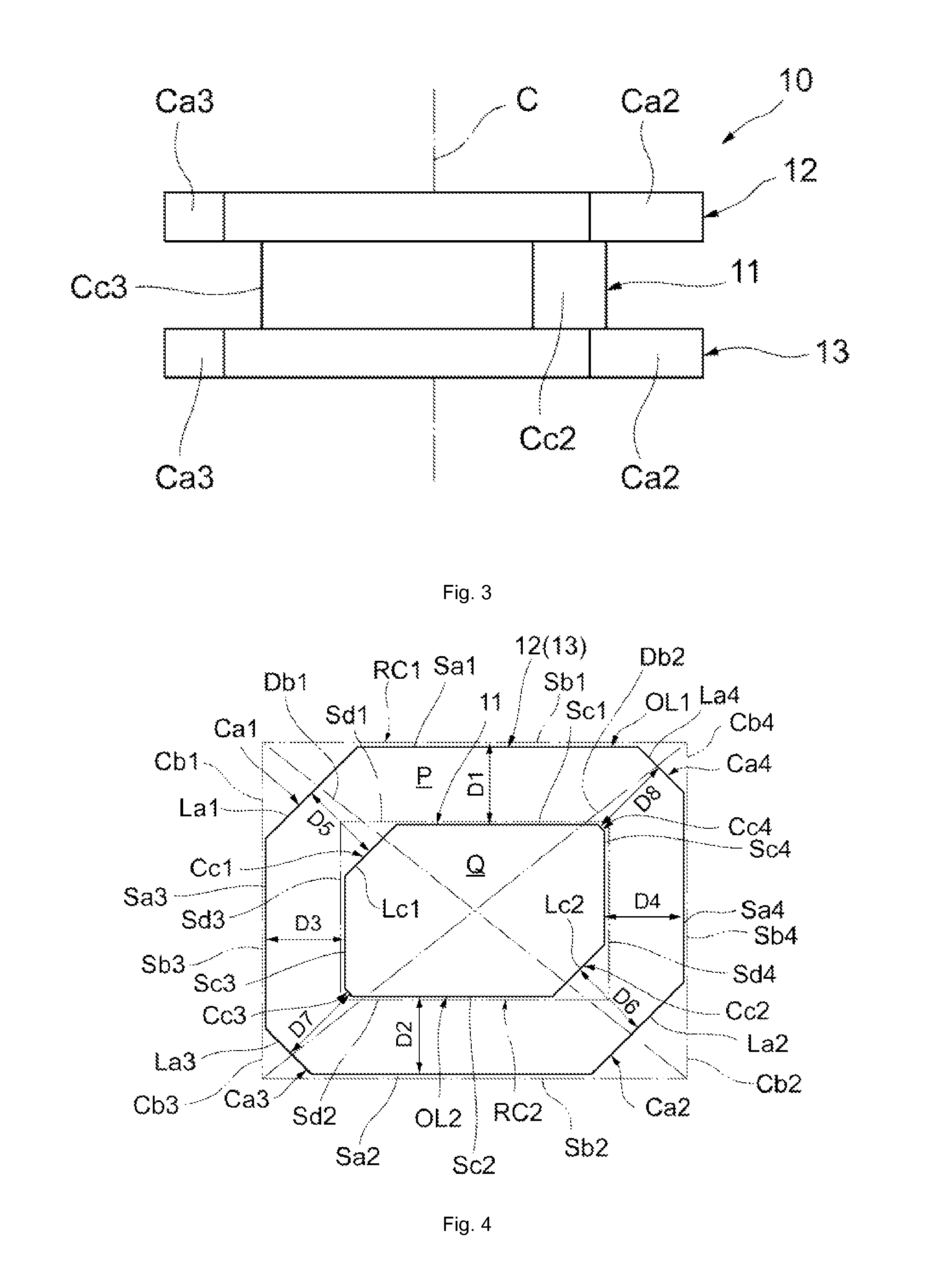
[0061]As shown in FIGS. 1 to 3, a magnetic core 10 relating to one exemplified embodiment of the present invention is constituted such that a winding core portion 11, a first flange portion 12 arranged on one axial end side (one end side in axis line C direction) of this winding core portion 11 and a second flange portion 13 arranged on the other axial end side (the other terminal side in axis line C direction) of the winding core portion 11 are formed integrally with one another. The first flange portion 12 and the second flange portion 13 are formed to be in rectangular-cylinder shapes having same sizes and same shapes as each other, and also the winding shaft portion 11 is formed to be in a rectangular-cylinder shape (details of the cross-secti...


PUM

PropertyMeasurementUnit
anglesaaaaaaaaaa
magneticaaaaaaaaaa
shapeaaaaaaaaaa

Abstract

A magnetic core including a winding core portion; and a flange portion provided on the axial end side of at least one of the winding core portion, wherein the flange portion is formed such that contour line OL1 of cross-section P, of the flange portion, which becomes perpendicular with respect to the axis line of the winding core portion forms a shape of a first irregular convex polygon which is substantially a non-regular polygon and also a convex polygon, and the contour line OL1 contacts with respect to all of sides Sb1, Sb2, Sb3 and Sb4 which are the four sides of a first circumscribed rectangle which becomes minimum within imaginary rectangles circumscribed with the contour line OL1 and also, the contour line OL1 includes side Sa1 and side Sat which respectively overlap with portions of respective ones of the side Sb1 and the side Sb2.

Description

CROSS REFERENCES TO RELATED APPLICATIONS[0001]The present invention contains subject matter related to Japanese Patent Application JP2012-200091 filed in the Japanese Patent Office on Sep. 12, 2012, the entire contents of which being incorporated herein by reference.BACKGROUND OF THE INVENTION[0002]1. Field of the Invention[0003]The present invention relates to a magnetic core having a winding core portion and a flange portion, a magnetic component using such a magnetic core, and a design method of a magnetic core.[0004]2. Description of the Related Art[0005]In the past, there have been known a magnetic core provided with flange portions at both end portions of a winding core portion around which a conductive wire is wound, and a magnetic component using such a magnetic core. For example, in Patent Document 1 (Japanese unexamined patent publication No. 2007-173573), there is disclosed a magnetic component (inductor) using a magnetic core provided with disk-like flange portions at bo...

Claims


Application Information

Patent Timeline
Patent Type & Authority Patents(United States)
IPC IPC(8): H01F27/02H01F3/08H01F17/04H01F27/28H01F27/24H01F5/00H01F27/29H01F17/06H01F27/06H01F41/02
CPCH01F27/29H01F41/0206H01F3/08Y10T29/4902H01F17/045H01F27/292
Inventor OKI, JUICHI
Owner SUMIDA CORP
Why Eureka
Try Eureka