Lens system, and objective lens system and optical projection system using the same

a technology of optical projection system and lens system, which is applied in the field of lenses system, can solve the problems of limiting the possibility of increasing the magnifying power of the object, lowering the quality of images projected onto the screen, and disabling the use of the object in compact optical devices, so as to achieve correct aberration, improve quality, and improve quality

Active Publication Date: 2006-06-27
SAMSUNG ELECTRONICS CO LTD
View PDF3 Cites 0 Cited by
  • Summary
  • Abstract
  • Description
  • Claims
  • Application Information

AI Technical Summary

Benefits of technology

[0015]The present invention also provides an objective lens system using the lens system, which can form a higher quality image on a screen with a larger field-of-view and correct aberrations.

Problems solved by technology

However, when applying the conventional lens system to an objective lens system, there are considerable limitations on the correction of aberrations occurring due to the diameter of the optical system pupil since an element that is closest to the image plane is the double-convex lens, further limiting the possibility of increasing objective magnifying power.
In addition, the conventional lens system cannot fully compensate for chromatic aberration, thereby lowering the quality of images projected onto a screen.
Furthermore, as the lens in the form of a meniscus is faced concave to the image surface, the field-of-view of the objective becomes significantly narrower, thereby disabling the use of the objective in compact optical devices, due to its curvature.
However, a refractive index of acryl material varies depending on temperature, so that focal points of the optical elements made of acryl material shift depending on temperature, thereby causing a defocusing or hindering a sharp focusing of the overall lens system.
However, the corrector lens unit of the lens system disclosed in U.S. Pat. No. 4,776,681 has a lens having a convex surface of very large radius of curvature close to a screen, so that the field-of-view becomes too narrow to be applied to smaller optical devices.

Method used


Image

  • Lens system, and objective lens system and optical projection system using the same
  • Lens system, and objective lens system and optical projection system using the same
  • Lens system, and objective lens system and optical projection system using the same

Examples


Embodiment Construction

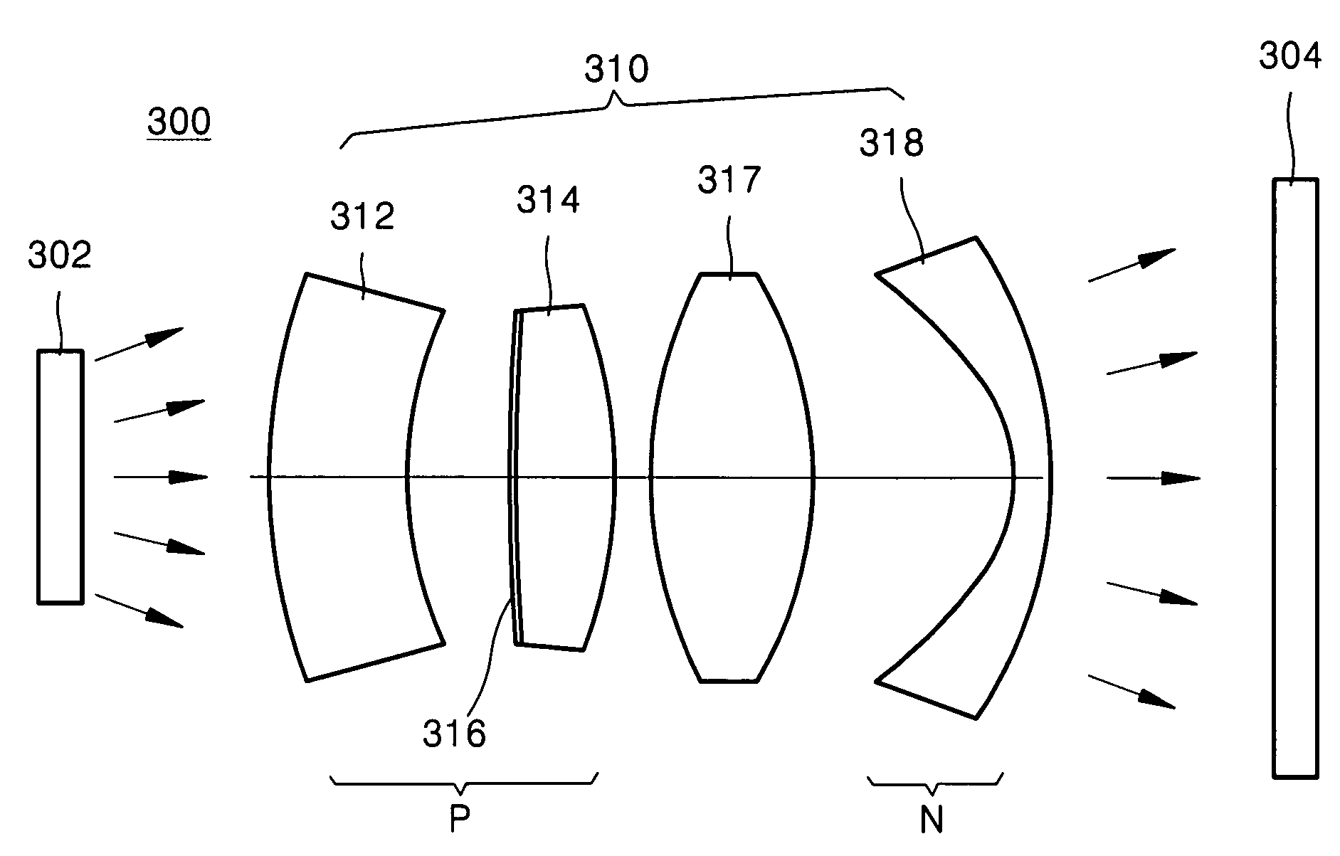
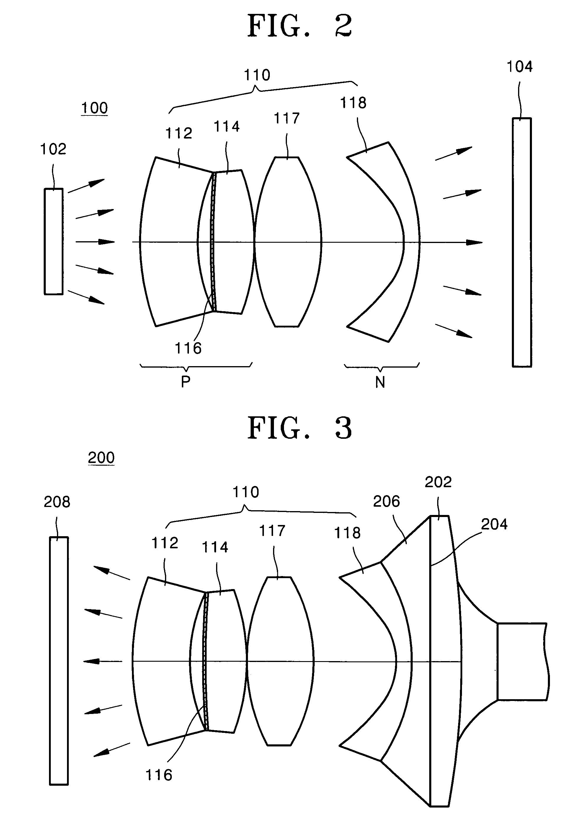
[0029]An objective lens system using a lens system according to an embodiment of the present invention is illustrated In FIG. 2. As illustrated in FIG. 2, an objective lens system 100 according to an embodiment of the present invention includes an object 102, a lens system 110, which includes a positive component P having a positive refractive index, an auxiliary element 117, and a negative element N having a negative refractive index, and an image plane 104. The positive component P includes a first negative lens 112, a double-convex lens 114, and a holographic optical element (HOE) 116, which is formed on a surface of the double-convex lens 114 adjacent to the first negative lens 112.

[0030]The term “positive component” used throughout the specification means a group of optical elements that converges a light beam passing therethrough toward an optical axis.

[0031]In the embodiment illustrated in FIG. 2, the first negative lens 112 is positioned adjacent to the object 102, and the n...


PUM


Abstract

A lens system which compensates for various aberrations, including chromatic aberration, with an enlarged field-of-view. The lens system includes a positive element and a negative element, each positioned in an optical path of incident light. The positive element includes a first negative lens, a convex lens and a hologram optical element. The negative element includes a second negative lens.

Description

[0001]This application claims priority to benefit of Russian Patent Application No. 2003105184, filed on Feb. 18, 2003, and Russian Patent Application No. 2003107773, filed on Mar. 17, 2003, in the Russian Intellectual Property Office, the disclosures of which are incorporated herein by reference.BACKGROUND OF THE INVENTION[0002]1. Field of the Invention[0003]The present invention relates to a lens system, and more particularly, to a lens system capable of compensating for chromatic aberration and enlarging the field-of-view, and an objective lens system and an optical projection system using the lens system.[0004]2. Description of the Related Art[0005]In general, objective lens systems or optical projection systems used in various optical displays or optoelectronic devices include a lens system. A conventional lens system includes an optical element having a small magnifying power for aperture aberration correction, which is arranged closer to an image plane, a double-convex lens, ...

Claims


Application Information

Patent Timeline
Patent Type & Authority Patents(United States)
IPC IPC(8): G02B3/00G02B5/32G02B15/16G02B9/58G02B13/00G02B13/16G02B27/00
CPCG02B9/58G02B27/4211G02B27/0037G02B13/16G02B5/1895G02B5/32G02B9/34H04N5/74G02B3/0087G02B1/041G02B3/04G02B2003/0093
Inventor GAN, MIKHAIL ABRAMOVICHBARMICHEVA, GALINA VICTOROVNA
Owner SAMSUNG ELECTRONICS CO LTD
Why Eureka
Try Eureka