System and method to estimate the location of a receiver

a receiver and location technology, applied in the field ofsignal processing, can solve the problems of inability to estimate the location of a receiver, inability to search for a long time, and inability to search in attenuated environments,

Inactive Publication Date: 2006-06-27
CSR TECH INC
View PDF13 Cites 14 Cited by
  • Summary
  • Abstract
  • Description
  • Claims
  • Application Information

AI Technical Summary

Benefits of technology

[0014]Techniques are provided that aid in determining the location of a signal receiver based on sampled data arising from a received signal that contains location-determining signals and noise. According to one aspect of the invention, the sampled data is processed with special probes performed at a sequence of points with increasing lengths between them. Bounds for the delay value and bounds for the modulation frequency value of the received signal are calculated for each signal source from a set of signal sources that are potentially detectable at the signal receiver. An estimate (“nominal value”) for the delay value...

Problems solved by technology

In addition to the frequency uncertainty, there is an uncertainty introduced due to the unknown propagation delay from the signal source to the receiver.
The initial problem of acquiring a signal therefore involves a search over the exact modulation frequency and the delay to the signal source.
A significant disadvantage of the above approach to acquisition is that it might have to search for a long amount of time before it has acquired enough signals to proceed.
These two problems combine to make search in attenuated environments prohibitively expensive in terms of either required delays or the number of independent channels needed to acquire the signals.
Furthermore, the independence of the channels for each signal in the acquisition phase does not leverage the calculations for the clock Doppler and delay values performed with respect to one signal source to aid the calculations with respect to another signal source.
This approach suffers from the drawback of having to wait for the time-stamp in the data message before giving even an initial position fix.
This means that even if the receiver is able to acquire all the satellites instantly, it still might have to wait up to a few seconds before being able to give any position estimate at all.
Some of these difficulties are partially mitigated by the techniques of assisted GPS but many of them remain problematic, especially in challenging attenuated environments such as urban buildings.
In such environments, the traditional assisted GPS technologies become impractical due to the computation expense and / or the for very long sampling times.

Method used


Image

  • System and method to estimate the location of a receiver
  • System and method to estimate the location of a receiver
  • System and method to estimate the location of a receiver

Examples


Embodiment Construction

[0025]In the following description, for the purposes of explanation, numerous specific details are set forth in order to provide a thorough understanding of the present invention. It will be apparent, however, to one skilled in the art that the present invention may be practiced without these specific details. In other instances, well-known structures and devices are shown in block diagram form in order to avoid unnecessarily obscuring the present invention.

System Overview

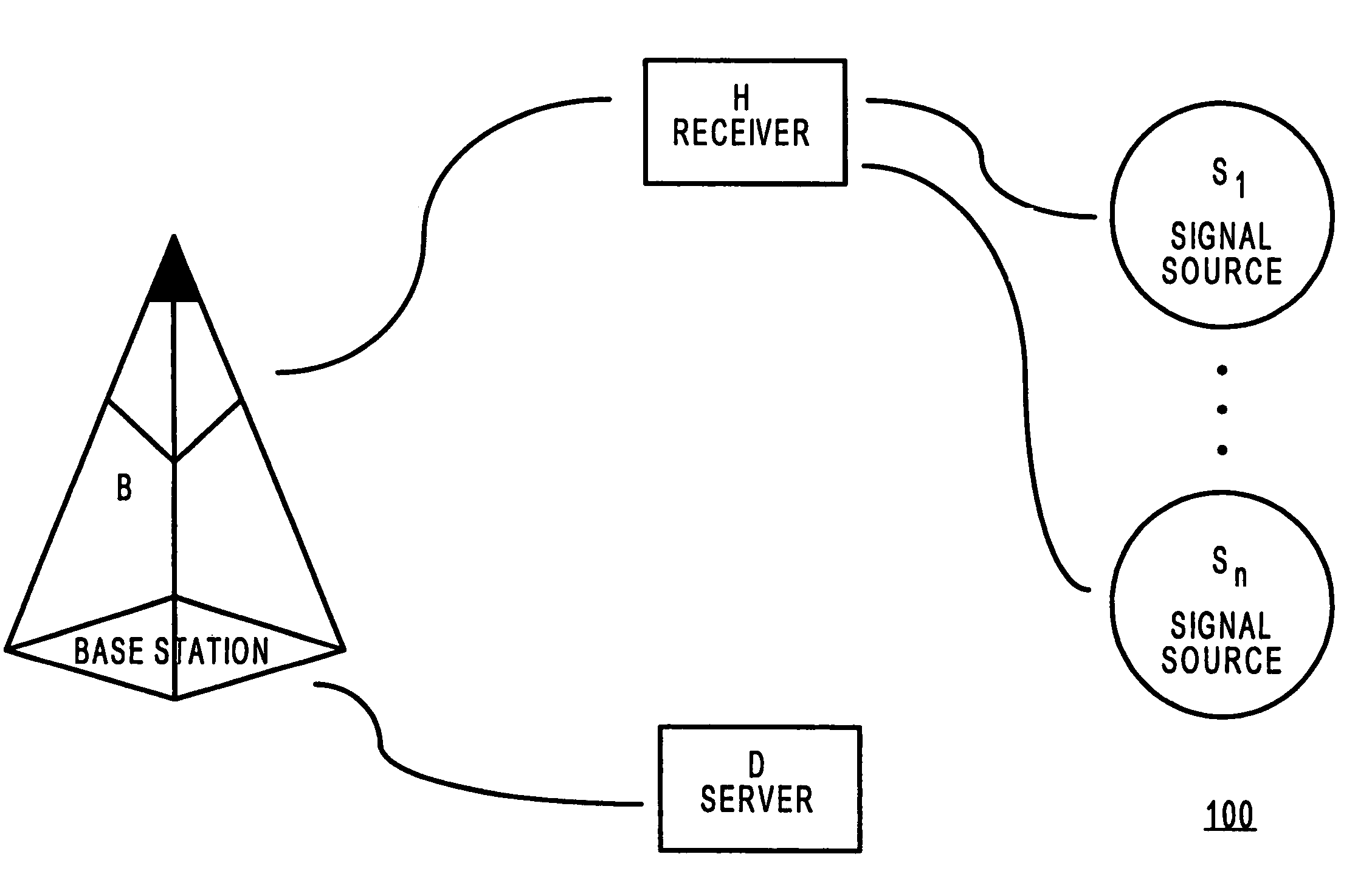
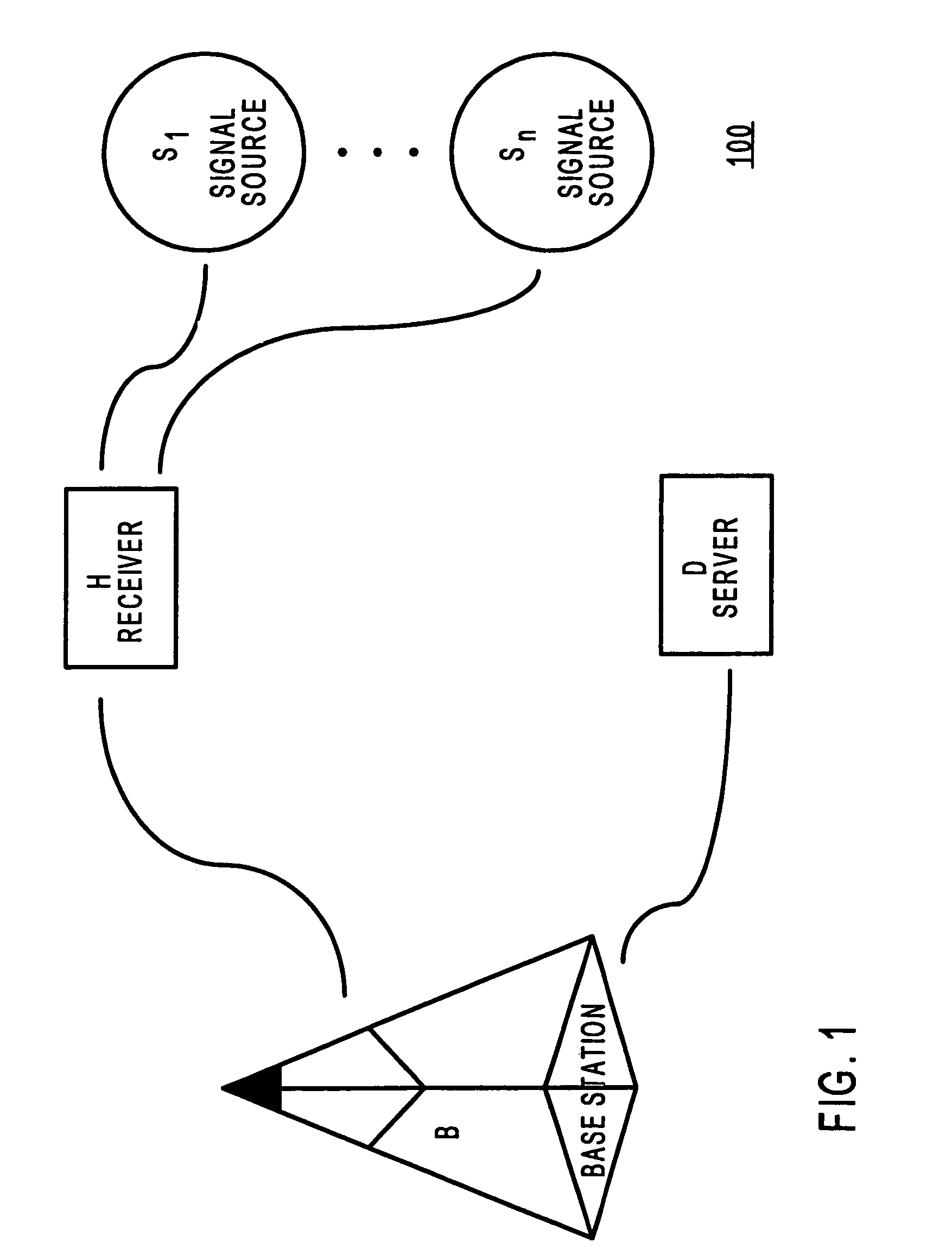
[0026]FIG. 1 is a block diagram that illustrates a system overview for determining the location of a receiver. System 100 comprises a plurality of signal sources of which only signal sources S1 and Sn, are shown in FIG. 1. In addition, system 100 comprises a receiver H, a base station B, and a server D.

[0027]By way of example, only one base station and one server are shown in system 100. For example, in a practical system, there may be multiple base stations and multiple servers. In other embodiments of the inventi...


PUM


Abstract

System and method to determine the location of a receiver are provided. The received signal is decomposed into signal chunks that are then correlated with the reference signals of the transmitting sources. In some embodiments, the signal chunks may be shorter than the period of the reference signals. For each signal source, a grid of correlation values is constructed containing one column of correlation values for each signal chunk. Each column contains correlation values for several code-phases. Probes are executed in the grid to acquire the location-determining signals. In some embodiments, a probe includes calculating the fourier transform of a row in the grid, yielding correlation values associated with a refined set of frequency values. Potential acquisitions are verified by processing increasing portions of the received signal. Confirmed acquisition may be used to aid further acquisitions. Some embodiments eventually compress the received signal down to a one period duration by means of an ultra-stacking method. Additional verification, comprising multi-peak test and multi-path tests, may be performed on the correlation magnitude curve obtained from the ultra-stacked signal. Finally, refined code-phase values are extracted from these correlation magnitude curves.

Description

CROSS REFERENCE TO RELATED APPLICATIONS[0001]This application claims the benefit of U.S. Provisional Application No. 60 / 318,538, filed Sep. 8, 2001, entitled “Ultrastacked refinement, frequency-following probes, sub-millisecond chunking, and mixed references for position determination”.FIELD OF THE INVENTION[0002]The present invention relates to signal processing and, more particularly, to techniques helpful in determining the location of a signal receiver.BACKGROUND OF THE INVENTION[0003]The location of a device may be determined using a global positioning system (“GPS”). In a general GPS system, a receiver acquires signals from four or more satellite vehicles to obtain a three dimensional location and a time stamp. A receiver may employ multiple channels and the received signal in each channel may be used to acquire a signal from a single signal source. After acquisition, a delay-locked loop is traditionally used to track the signal source and is used to give updates to the receiv...

Claims


Application Information

Patent Timeline
IPC IPC(8): H04Q7/20G01S1/00G01S19/37
CPCG01S19/30G01S19/29G01S19/09G01S19/22
Inventor SAHAI, ANANTCHOU, ANDREW
Owner CSR TECH INC
Why Eureka
Try Eureka