Position sensing system

a position sensor and sensing technology, applied in the direction of optical radiation measurement, navigation instruments, instruments, etc., can solve the problems of adversely affecting, intrinsically analog, and extreme environmental stress of conventional position sensors (e.g. located on the wings of aircraft)

Active Publication Date: 2006-06-27
ROCKWELL COLLINS INC
View PDF5 Cites 35 Cited by
  • Summary
  • Abstract
  • Description
  • Claims
  • Application Information

AI Technical Summary

Benefits of technology

[0005]Yet another exemplary embodiment of the invention relates to a system for determining a physical position of a flight control surface of an aircraft. The system comprises means for transmitting an incident pulse of light. The system also comprises means for dividing the incident pulse of light into a plurality of incident pulses of light. The system also comprises means for reflecting the incident pulses of light and for providing a plurality of reflected pulses of light. The system also comprises means for delaying the incident pulses of light and for delaying the reflected pulses of light. The system also comprises means for detecting the reflected pulses of light. A signal encoded in a binary format and representative of the physical position of the flight control surface is provided to the means for detecting the reflected pulses of light.
[0006]Still another exemplary embodiment of the invention relates to a method for determining a physical position of a flight control surface of an aircraft. The method comprises transmitting an incident pulse of light from a light source through a primary optical path and subsequently dividing the incident pulse of light into a plurality of incident pulses of light. The method also comprises transmitting the incident pulses of light through a plurality of secondary optical paths. The method also comprises reflecting the incident pulses of light with a reflector. The method also comprises transmitting the reflected pulses of light through the plurality of optical paths and subsequently transmitting the reflected pulses of light through the secondary path. The method also comprises detecting the reflected pulses of light with a control system having a photodetector. An encoded signal representative of the physical position of the flight control surface is read by the control system.
[0007]Another exemplary embodiment of the invention relates to a passive sensing system for determining a physical position of a flight control surface of an aircraft. The sensing system comprises an encoding system configured to provide a signal encoded in a binary format and representative of the physical position of the flight control surface. The sensing system also comprises a single fiber optic cable having a first diameter and coupled between a light source and the encoding system. The sensing system also comprises a plurality of fiber optic cables each having a second diameter less than the first diameter and configured for coupling to an end of the single fiber optic cable. An illumination pulse from the light source is divided into a plurality of pulses by the plurality of fiber optic cables.

Problems solved by technology

Hence, such conventional position sensors (e.g. located on the wings of the aircraft) are subject to extreme environmental stress including electrical phenomena such as lightning and high intensity radiated fields (“HIRF”), as well as temperature, vibration, moisture, dirt, etc.
Such conventional position sensors have several disadvantages including that they are intrinsically analog (i.e. include an electrical circuit having an output that is proportional to the input) and are adversely affected by electrical noise interference.

Method used


Image

  • Position sensing system
  • Position sensing system
  • Position sensing system

Examples


Embodiment Construction

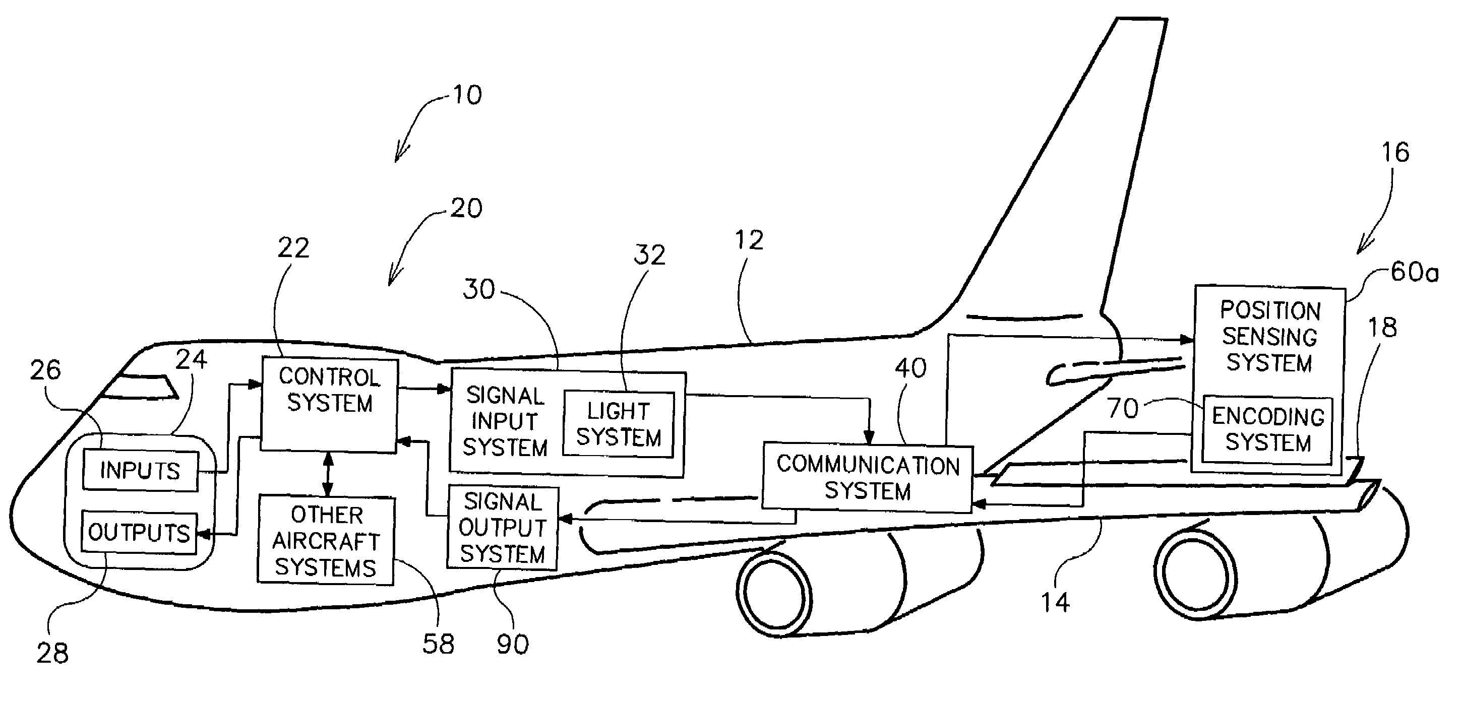
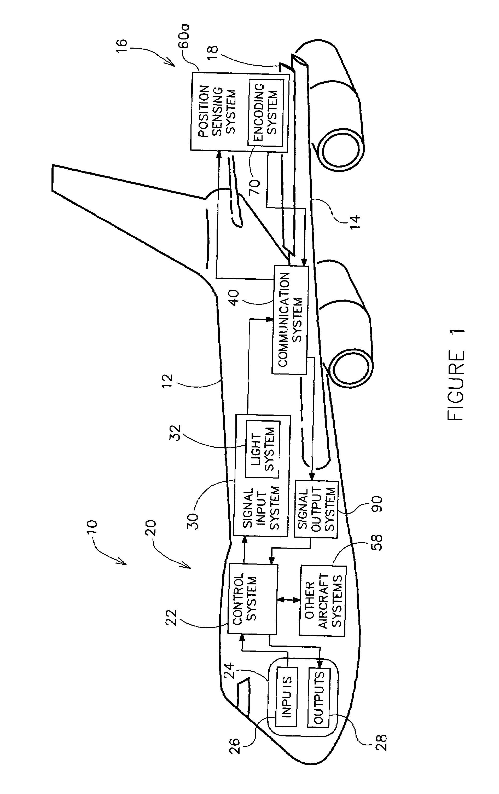
[0020]Referring to FIG. 1, a sensing system 20 having a position sensing system 60a is shown according to an exemplary embodiment. The sensing system is useful for detecting the physical position of mechanical devices in high power and high electrical noise environments (e.g. industrial controls applications where large motors, induction furnaces, etc. may be present, control rods in nuclear reactors, the thickness of rollers in steel mills, etc.). As shown in FIG. 1, sensing system 60a is adapted to provide an encoded signal representative of a physical position of a flight control surface 16 of an aircraft 10 (shown as an aileron 18 of a wing 14).

[0021]Position sensing system 60a is located outboard or outside a main body or pressure envelope 12 of aircraft 10 as shown in FIG. 1 according to a preferred embodiment. An optical encoding system 70 of sensing system 20 is configured to encode the signal representative of the physical position of flight control surface 16 into a binary...


PUM


Abstract

A passive sensing system for determining a physical position of a mechanical device includes an encoding system configured to convert a position signal representative of the physical position of the mechanical device into an encoded signal in a binary format. The sensing system also comprises a plurality of secondary optical paths coupled to a primary optical path positioned between a light source and the encoding system. The encoded signal comprises a plurality of pulses of light each sequentially delayed by the secondary optical paths. A system for determining a physical position of a flight control surface of an aircraft is also disclosed. A method for determining a physical position of a flight control surface of an aircraft is also disclosed. A passive sensing system for determining a physical position of a flight control surface of an aircraft is also disclosed.

Description

FIELD OF THE INVENTION[0001]The present invention relates to a position sensing system. More particularly, the present invention relates to a passive optical position sensor. More particularly, the present invention relates to an optical sensor for determining the position of a mechanical device. More particularly, the present invention relates to a fiber optic position sensor for determining the physical position of a flight control surface of an aircraft.BACKGROUND OF THE INVENTION[0002]It is generally known to provide a position sensor, such as for an aircraft. Such conventional position sensors provide signals representative of the physical position of a “flight control surface” of the aircraft. An exemplary flight control surface includes an aileron used to control rolling and banking movements of the aircraft. Such conventional position sensors are typically located outside the main body or pressure envelope of the aircraft. Hence, such conventional position sensors (e.g. loca...

Claims


Application Information

Patent Timeline
Patent Type & Authority Patents(United States)
IPC IPC(8): G05D1/00
CPCG01D5/34776
Inventor KOENCK, STEVEN E.PENG, GUOLINJENSEN, DAVID W.ARUNDALE, GREGORY A.
Owner ROCKWELL COLLINS INC
Why Eureka
Try Eureka