Remedial system to flush contaminants from tubing string

a technology of contaminated tubing and rebar, which is applied in the direction of drilling casings, drilling pipes, borehole/well accessories, etc., can solve the time-consuming problem of pulling the top drive motor assembly, and achieve the effect of more rigidity

Active Publication Date: 2006-07-04
VETCO GRAY LLC
View PDF7 Cites 45 Cited by
  • Summary
  • Abstract
  • Description
  • Claims
  • Application Information

AI Technical Summary

Benefits of technology

[0006]A method of treating a well is provided with this invention. A string of production tubing is suspended within casing in a well. A pump is located at a lower end of the tubing for pumping well fluid through the tubing to a wellhead at the surface. A closure member is connected to a...

Problems solved by technology

While this technique is workable, pulling...

Method used


Image

  • Remedial system to flush contaminants from tubing string
  • Remedial system to flush contaminants from tubing string
  • Remedial system to flush contaminants from tubing string

Examples


Embodiment Construction

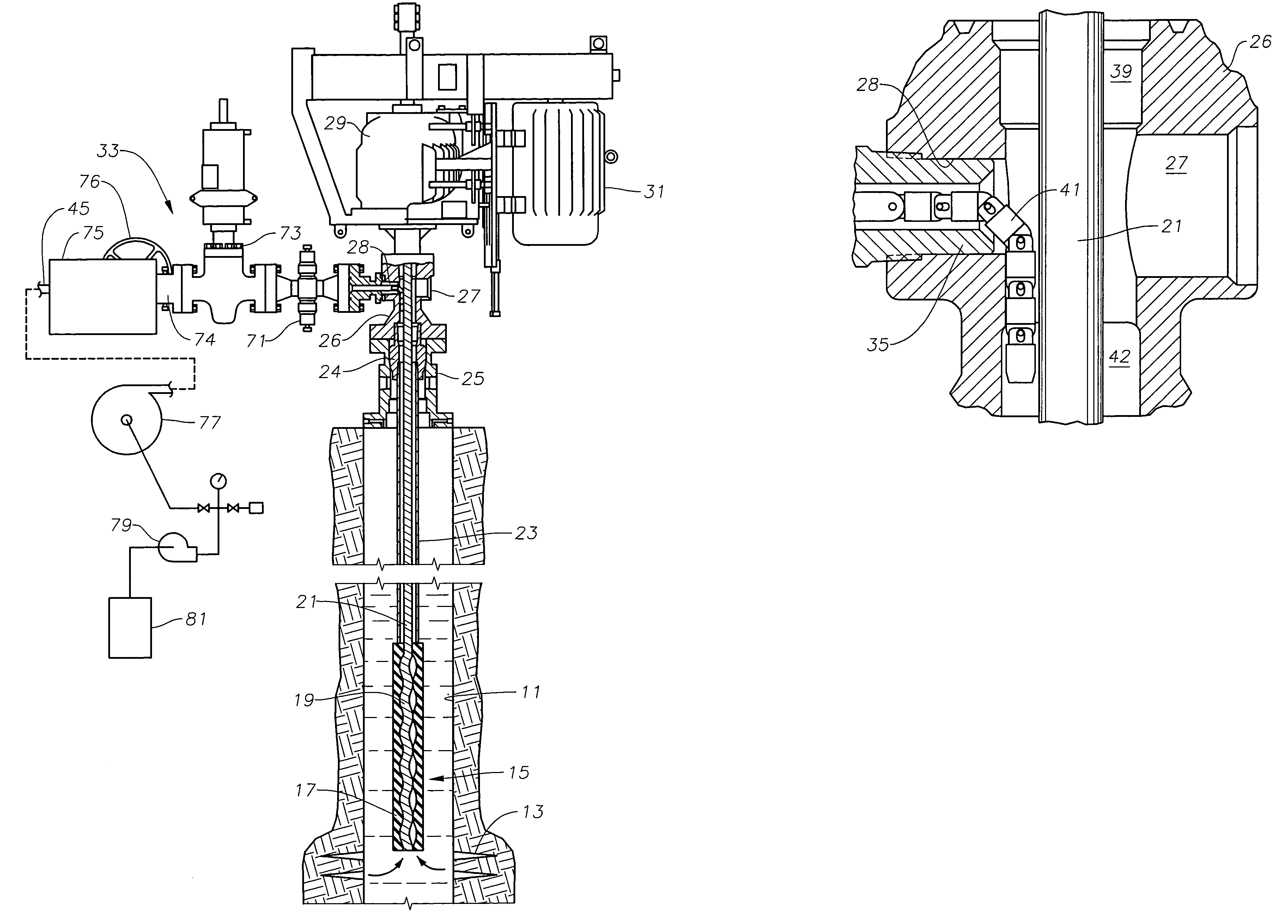
[0011]Referring to FIG. 1, a well has a casing 11 with perforations 13 to enable well fluid to flow into casing 11. A conventional progressive cavity pump 15 is shown suspended in casing 11 for pumping the well fluid to the surface. Pump 15 includes a stator 17 that comprises a stationary housing having an elastomeric interior. The elastomeric interior is formed with helical cavities. A metal rotor 19 is located inside stator 17 and rotated to cause fluid to pump through progressive cavity pump 15. Rotor 19 has a helical exterior.

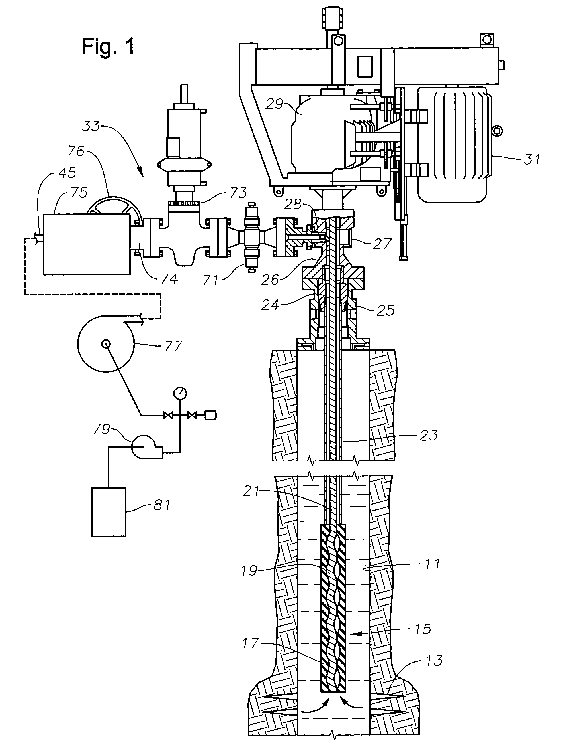
[0012]In this embodiment, rotor 19 is rotated by a string of sucker rods 21 that extend to the surface through a string of production tubing 23. Tubing 23 is suspended on a tubing hanger 24 landed in a tubing head 25. A blowout preventer 26 mounts on top of tubing head 25, the two components forming a wellhead for the well. Blowout preventer 26 comprises a tubular housing, typically with a manually operable set of rams that will close around rods 21 in the ...


PUM


Abstract

A method of cleaning debris from a string of production tubing in a well enables removal without pulling the string of rods that extend through the tubing. A rotary pump is suspended to a lower end of the tubing for pumping well fluid through the tubing to a wellhead at the surface. A motor assembly at the surface rotates the rods to drive the pump. A closure member is placed on a lower end of an elastomeric hose that will open when a selected level of internal fluid pressure is applied. The operator applies internal pressure to the hose at a pressure less than the selected level to increase rigidity of the hose. The operator inserts the hose through a port in a sidewall of the wellhead, the hose deflecting downward and into the tubing. At a desired point, the operator increases the internal pressure in the hose to open the closure member, then discharges a cleansing fluid into the tubing, which flows back up the tubing along with debris.

Description

[0001]This application claims the priority of provisional application Ser. No. 60 / 463,223, filed Apr. 16, 2003, entitled “Remedial System to Flush Contaminants From a Tubing String”.FIELD OF THE INVENTION[0002]This invention relates in general to oil well production, and in particular to a system using an elastomeric hose for insertion into a tubing string to remove contaminants.BACKGROUND OF THE INVENTION[0003]One type of well has part of a rotary pump, such as a progressive cavity pump stator, secured to a lower end of a string of tubing. The tubing is located within casing, and the upper end of the tubing is supported in a wellhead at the surface. A motor assembly located at the surface is coupled to a string of rods that lead through the tubing. A rotor on the lower end of the rods fits within the pump stator. The motor assembly rotates the rods and the rotor to cause the pump to deliver well fluid up the tubing to the surface. These wells are usually shallow, and the well fluid...

Claims


Application Information

Patent Timeline
IPC IPC(8): E21B37/00E21B21/00E21B33/03E21B33/068
CPCE21B37/00E21B33/068
Inventor CHAN, KWONG-ONN C.SEDGWICK, DAVID J.COMEAUX, DAVIDMURPHY, JOHN
Owner VETCO GRAY LLC
Why Eureka
Try Eureka