Leg press and abdominal crunch exercise machine

a technology of exercise machine and leg press, which is applied in the direction of gymnastic exercise, weights, sport apparatus, etc., can solve the problems of cumbersome linkage between the four bar linkage of the leg press and the resistance force used as a resistance force, not providing the most effective exercise results for users, and a user's difficulty in starting the exercis

Inactive Publication Date: 2006-07-04
NAUTILUS INC
View PDF671 Cites 102 Cited by
  • Summary
  • Abstract
  • Description
  • Claims
  • Application Information

AI Technical Summary

Benefits of technology

[0008]The combination of the first four bar linkage system and the second four bar linkage system can be viewed as a force conditioning device. In fact, a force conditioning device as disclosed herein may be a system employing more than four bars operably connected together to provide a mechanical advantage to a first force acting on the device in opposition to a second force acting on the device.
[0009]In another embodiment of the invention, the exercise machine is composed of a frame supporting a first four bar linkage system and a second four bar linkage system. The first four bar linkage system is composed of a first substantially vertical member and a second substantially vertical member spaced apart from the first vertical member. The first member and second member are operably mounted at their lower ends to a portion of the frame in a first spaced relation to each other. The second four bar linkage system operably engages the first four bar linkage system and is actually composed of a portion of the first four bar linkage system plus additional components. The additional components of the second four bar linkage system are a third member operably engaged with at least one of the first member, the second member, the support member, and the frame; and a fourth member operably engaged with

Problems solved by technology

While providing an instantaneous axis of rotation for the foot plate, the linkage between the four bar linkage of the leg press and the weight stack used as a resistance force, although quite functional, is also quite cumbersome.
A flat force curve does not provide the most effect

Method used


Image

  • Leg press and abdominal crunch exercise machine
  • Leg press and abdominal crunch exercise machine
  • Leg press and abdominal crunch exercise machine

Examples


first embodiment

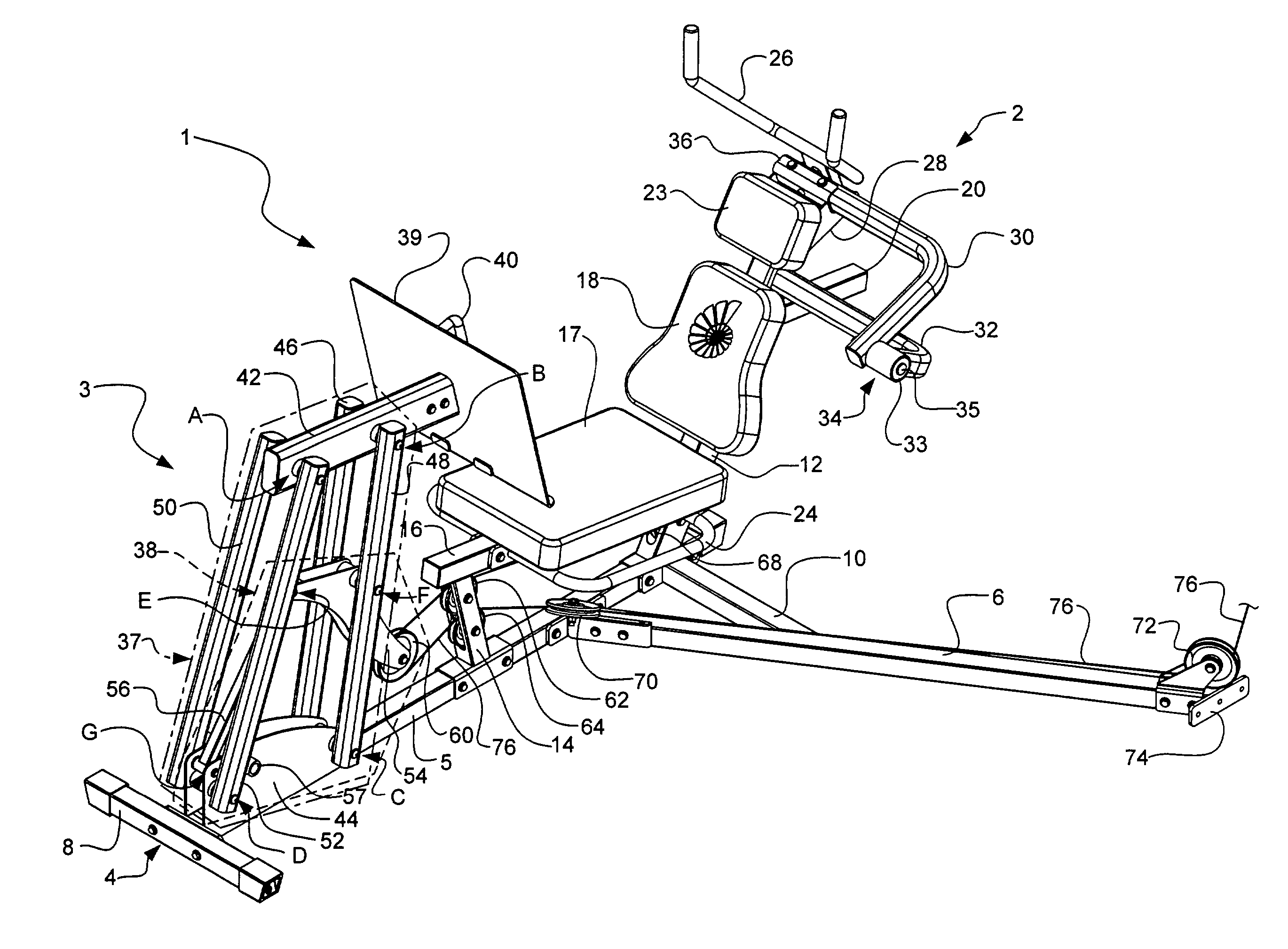
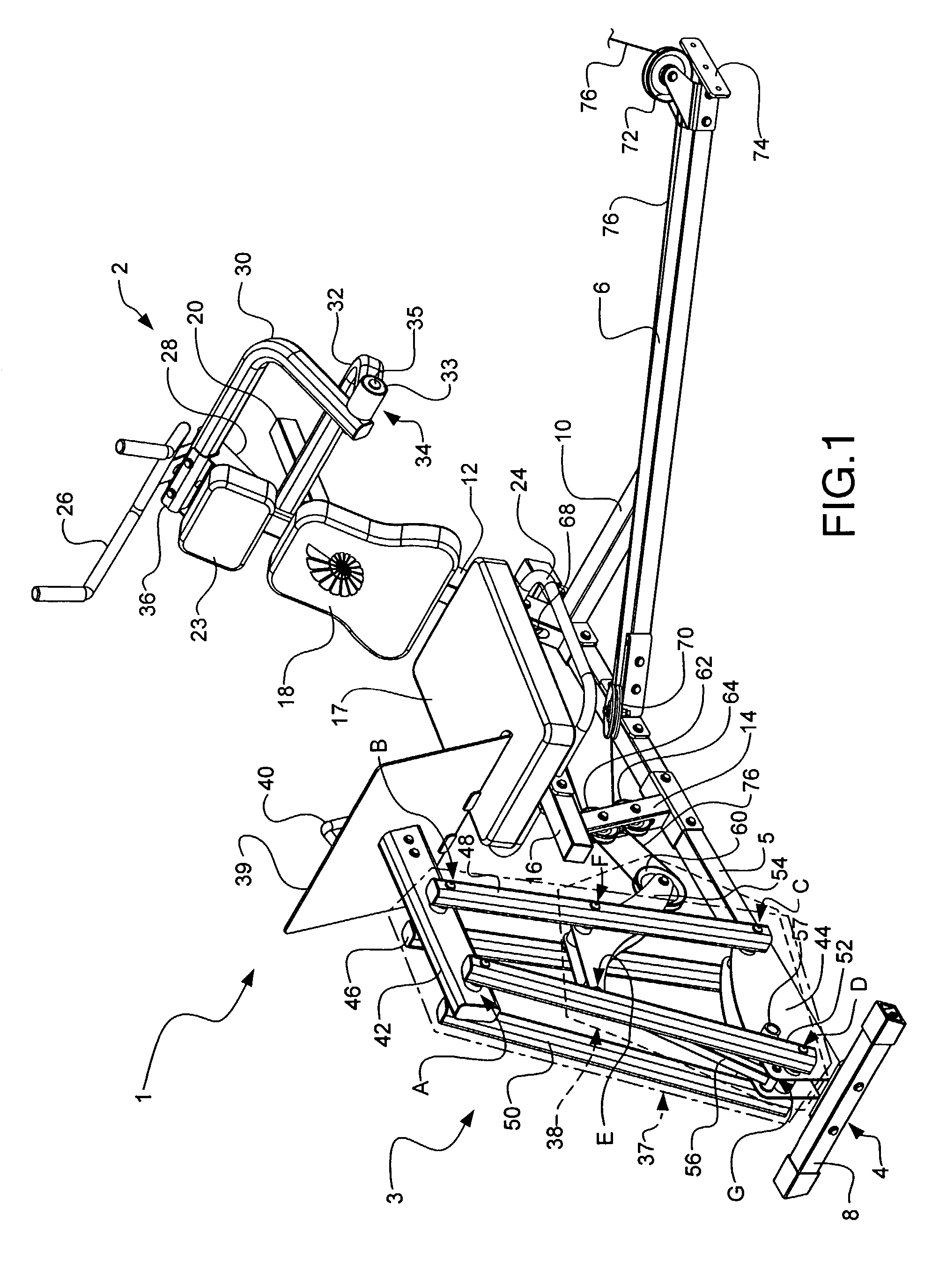
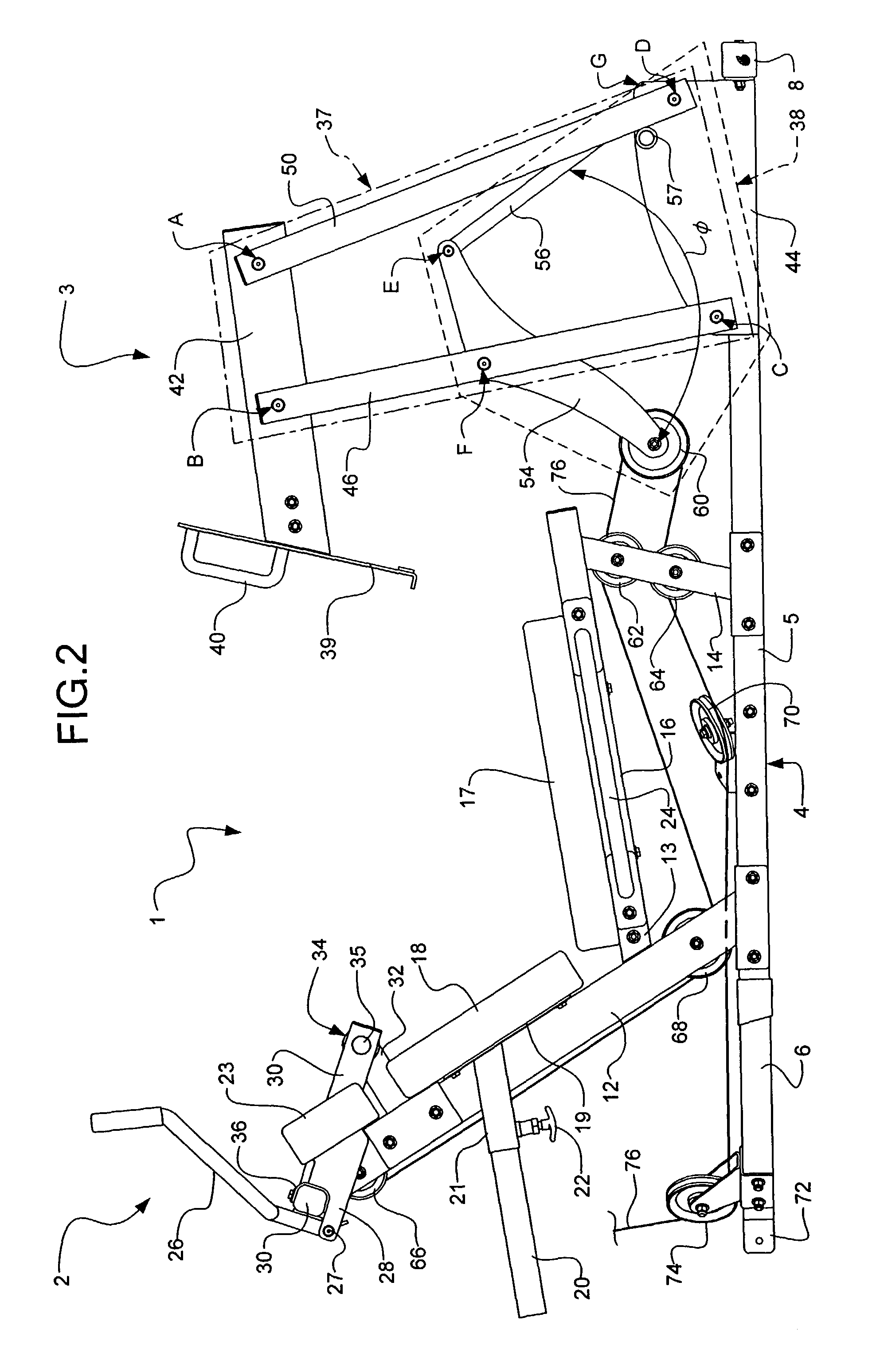
[0040]The leg press portion 3 of the exercise machine 1 is mounted on the frame 4 in front of the front seat post 14. The leg press portion 3 according to the exercise machine 1 is composed primarily of a first four bar linkage system 37, a second four bar linkage system 38, and a structure for engaging the feet or lower legs of the user, in this case, a foot plate 39. The first four bar linkage system 37 may be formed by two pairs of generally vertical bars: a left rear bar 46, a right rear bar 48, a left front bar 50, and a right front bar 52; a foot plate bar 42; and, in this exemplary embodiment, a riser frame 44. The left rear bar 46 and the right rear bar 48 may together be considered one of the four sides of the first four bar linkage system 37. In one exemplary embodiment, the left rear bar 46 and the right rear bar 48 may each be approximately 73.6 cm long between pivot point B and pivot point C. Similarly, the left front bar 50 and the right front bar 52 may together be co...

second embodiment

[0057]The top ends of the left rear bar 46, the right rear bar 48, the left front bar 50, and the right front bar 52 of the second embodiment may each be pivotally attached, generally transverse to the foot plate bar 42. The left front bar 50 and the right front bar 52 may be attached directly opposing each other on opposites sides of the foot plate bar 42 on an axel through the foot plate bar 42 at pivot point A. Likewise, the left rear bar 46 and the right rear bar 48 may be attached directly opposing each other on opposites sides of the foot plate bar 42 on an axel through the foot plate bar 42 at pivot point B. In the exemplary embodiment, the distance between pivot point A and pivot point B may be approximately 10.7 cm. The bottom ends of the left rear bar 46, the right rear bar 48, the left front bar 50, and the right front bar 52 may each be pivotally attached, generally transverse to a portion of the base rail 5. The left rear bar 46 and the right rear bar 48 may be attached...

third embodiment

[0069]the exercise machine 1 of the present invention is depicted in FIG. 19. This embodiment is configured for use, for example, with a circuit weight stack. The exercise machine 1 is built upon a frame 4. The frame 4 is composed of several sections, including a base rail 5, a handlebar post attachment rail (not shown), a handlebar support post 7, a rear support post 11, a rear support plate 9, a rear seat post 12, a front seat post 14, and a seat bar 16. The various bars and post that compose the frame 4 may be, for example, straight, tubular (e.g., round or square), metal (e.g., steel) beams that are attached together, for example, with brackets and through bolts. Such brackets may be separate pieces or integral with the various bars and posts.

[0070]The base rail 5 is the foundation of the frame 4 and generally rests flat upon a floor surface. The base rail 5 generally extends generally the length of the exercise machine 1 as shown in FIG. 19. This embodiment of the exercise mach...


PUM


Abstract

An exercise machine composed of a frame, a first four bar linkage system, a second four bar linkage system, and a means for transferring an incident force from the legs of a user is disclosed. The first four bar linkage system is operably mounted on the frame and operably connects the transferring means to the frame to allow for back and forth movement of the transferring means along a path of travel about an instantaneously changing axis of rotation. The second four bar linkage system operably engages the first four bar linkage system. Either or both of the first four bar linkage system and the second four bar linkage system are operably connected to a resistance means, whereby the second four bar linkage system operates in conjunction with the first four bar linkage system and the resistance means to create a mechanical disadvantage to the user.

Description

CROSS REFERENCE TO RELATED APPLICATIONS[0001]This application is a continuation-in-part of U.S. patent application Ser. No. 10 / 186,433, filed 1 Jul. 2002, entitled “Leg Curl / Leg Extension Weight Training Machine.” This application is also a continuation-in-part of U.S. patent application Ser. No. 10 / 192,330, filed 10 Jul. 2002, entitled “Leg Press Weight Training Machine.”BACKGROUND OF THE INVENTION[0002]1. Field of the Invention[0003]This invention relates to exercise equipment and machines for home commercial use.[0004]2. Description of the Related Art[0005]For example, commonly owned U.S. Pat. No. 5,106,081 to Webb discloses a leg press machine that incorporates a four bar linkage configuration for changing the angle of inclination of the foot plate to maintain a normal orientation to the lower legs of a user throughout the movement of the leg press exercise. While providing an instantaneous axis of rotation for the foot plate, the linkage between the four bar linkage of the leg ...

Claims


Application Information

Patent Timeline
IPC IPC(8): A63B21/06A63B21/062A63B23/02A63B23/04
CPCA63B21/062A63B23/0405A63B23/0211A63B21/0628
Inventor LULL, ANDREW P.WEBB, GREGORY M.
Owner NAUTILUS INC
Why Eureka
Try Eureka