Method and system for vehicle emission testing

a technology for vehicle emission testing and methods, applied in chemical methods analysis, liquid/fluent solid measurement, instruments, etc., can solve the problems of not representative of “real world” driving, different amount of labor and skill required to conduct testing and maintain equipment, and different reliability and accuracy of testing, so as to achieve low implementation, operating and maintenance costs

Inactive Publication Date: 2006-07-04
GORDON DARBY SYST
View PDF12 Cites 37 Cited by
  • Summary
  • Abstract
  • Description
  • Claims
  • Application Information

AI Technical Summary

Benefits of technology

[0019]The present invention is a method and system for vehicle emission testing that converts measured pollutant concentration into its corresponding pollutant mass at relatively low i

Problems solved by technology

Such variations often result in differences in the reliability and accuracy of the testing, along with differences in the amount of labor and skill required to conduct the testing and to maintain the equipment associated with that testing.
Although these two tests provide general baseline information regarding vehicle emissions, they are not representative of “real world” driving.
As a result, both the Idle Mode Test and the Loaded Mode Test often tend to produce false positives.
Quite clearly, such testing failures are potentially detrimental to the air quality of a geographic area because vehicles which require repair are not appropriately identified, thus allowing for excessive release of polluting emissions.
Such test methods are clearly preferred as compared to the Idle Mode Test and the Loaded Mode Test; however, along with improved performance comes increased costs.
Nevertheless, because the vehicles are artificially loaded and are not tested across a range of velocities, accelerations, and decelerations representative of “real world” driving conditions used to test and initially certify vehicles for sale, false failures can result.
In other words, a vehicle might fail the ASM concentration test even though that vehicle is in

Method used


Image

  • Method and system for vehicle emission testing
  • Method and system for vehicle emission testing
  • Method and system for vehicle emission testing

Examples


Embodiment Construction

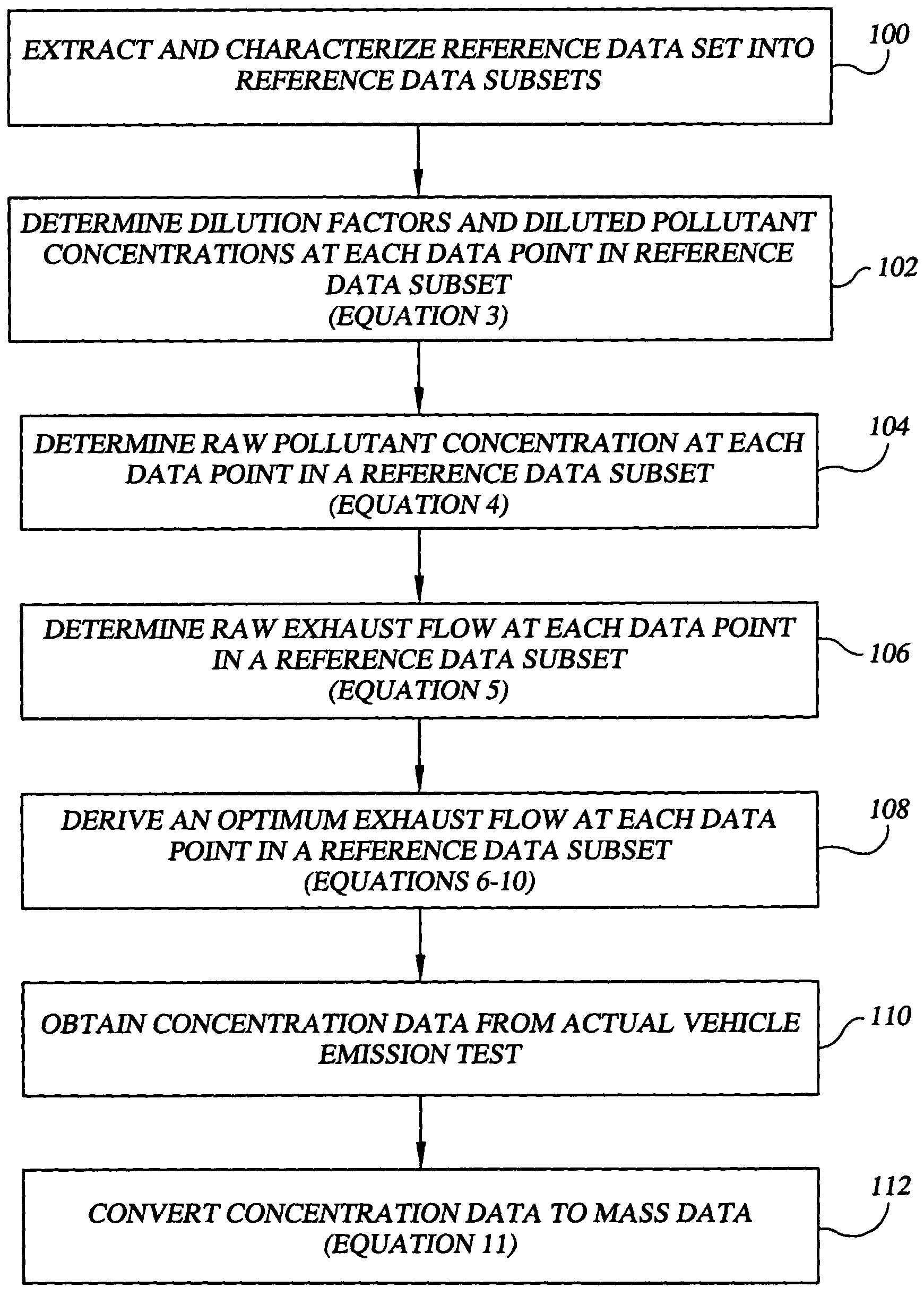
[0028]The present invention is a method and system for vehicle emission testing that converts measured pollutant concentration into its corresponding pollutant mass at relatively low implementation, operating, and maintenance costs. Specifically, the method and system of the present invention allows for the calculation of a vehicle's emissions (and resultant test scores) for one or more common pollutants in units of mass per distance, thus allowing for subsequent comparison of each such test score to a standard to determine if the vehicle has passed or failed the emissions test. Through the use of the method and system of the present invention, significantly more accurate results can be obtained as compared to Idle Mode, Loaded Mode, ASM, remote sensing and similar testing methods, but without the implementation, operating, and maintenance costs of TMEI.

[0029]As described above with reference to commonly assigned and co-pending U.S. application Ser. No. 09 / 851,192, it is possible to...


PUM

PropertyMeasurementUnit
Flow rateaaaaaaaaaa
Massaaaaaaaaaa
Concentrationaaaaaaaaaa

Abstract

A method and system for vehicle emission testing measures pollutant concentration, but then provides for conversion of the measured pollutant concentration into its corresponding pollutant mass, thereby allowing for the calculation of a vehicle's emission test scores for one or more common pollutants in units of mass per distance. Through the use of the method and system of the present invention, significantly more accurate results can be obtained as compared to prior art test methods, and without the implementation, operating, and maintenance costs of comparable test methods.

Description

CROSS-REFERENCE TO RELATED APPLICATIONS[0001]The present application is a continuation-in-part of U.S. Utility application Ser. No. 09 / 851,192 filed May 8, 2001, an application claiming priority to U.S. Provisional Patent Application Ser. No. 60 / 202,958 filed May 9, 2000 now U.S. Pat. No. 6,623,975. Each of the above-referenced applications is incorporated herein by reference.BACKGROUND OF THE INVENTION[0002]The present application relates to a method and system for vehicle emission testing. Vehicle emissions have long been identified as a major contributor to air pollution. As such, in geographical areas having particularly poor air quality, the United States federal government, through the Environmental Protection agency (“EPA”), has mandated vehicle emission inspection and maintenance programs. The intent or objective of these vehicle emission inspection and maintenance programs is to identify vehicles which are no longer performing acceptably, i.e., vehicles which are releasing ...

Claims


Application Information

Patent Timeline
IPC IPC(8): G01N33/22B32B5/02G01N33/00G01N33/497G01N7/00
CPCG01M15/102G01N1/2252G01N15/06Y10T436/218G01N2015/0693Y10T436/208339G01N2001/2264
Inventor TEFFT, ROBERT J.GORDON, S. JAYMAHAFFEY, CLIFTONAUSTIN, THOMAS C.CARLSON, THOMAS R.
Owner GORDON DARBY SYST
Why Eureka
Try Eureka