Set-top box having an improved patch antenna

a technology of patch antenna and set-top box, which is applied in the direction of television system, television system, printed circuit non-printed electric components association, etc., can solve the problems of reducing the performance of the antenna, reducing the usefulness or at least significantly of the antenna, and high cost of the cable, so as to reduce or eliminate the interfering effect

Inactive Publication Date: 2006-07-04
EAGLE BROADBAND
View PDF9 Cites 8 Cited by
  • Summary
  • Abstract
  • Description
  • Claims
  • Application Information

AI Technical Summary

Benefits of technology

[0013]Using a patch antenna as the set top box's antenna advantageously solves the problem of interference that would result from the metal enclosure if other types of antennas were used. Using a patch antenna and locating the patch antenna behind the bezel hides the antenna from the user's reach, thereby advantageously avoids the user from having to carefully place or adjust the antenna. Further, the patch antenna is optimized for use in a multi-dielectric constant environment. In addition, the choice of antenna (patch) and its orientation outside the metal enclosure reduces or eliminates interfering effects from the enclosure. These and other advantages will become apparent upon reviewing the following description and drawings.

Problems solved by technology

For instance, such systems traditionally require a large number of electrical cables to interface to the set top box.
Cables can be expensive and are generally cumbersome, unattractive, and often limited to small areas unless one is willing to run cables throughout the home or office.
There are a number of problems that must be addressed when choosing an appropriate antenna type and designing the particular antenna configuration.
Such design considerations include the desired frequency range, size and shape of the pattern of coverage of the antenna, and other issues.
Such metal surfaces can, to a certain extent, short circuit the antenna rendering it useless or at least significantly decreasing its performance.
First, the location of the antenna should not be inside the metal enclosure because of the problem noted above.
Second, if the antenna is placed on the outside of, but close to, the metal enclosure, the metal enclosure may still detrimentally interfere with the antenna's performance.
The patch antenna described therein, however, is unsuitable for use on a thin FR-4 circuit board.

Method used


Image

  • Set-top box having an improved patch antenna
  • Set-top box having an improved patch antenna
  • Set-top box having an improved patch antenna

Examples


Embodiment Construction

[0024]The following description describes the preferred embodiment of the invention in the context of a set top box. However, it should be noted that the antenna design shown below is not limited to just set top box technology.

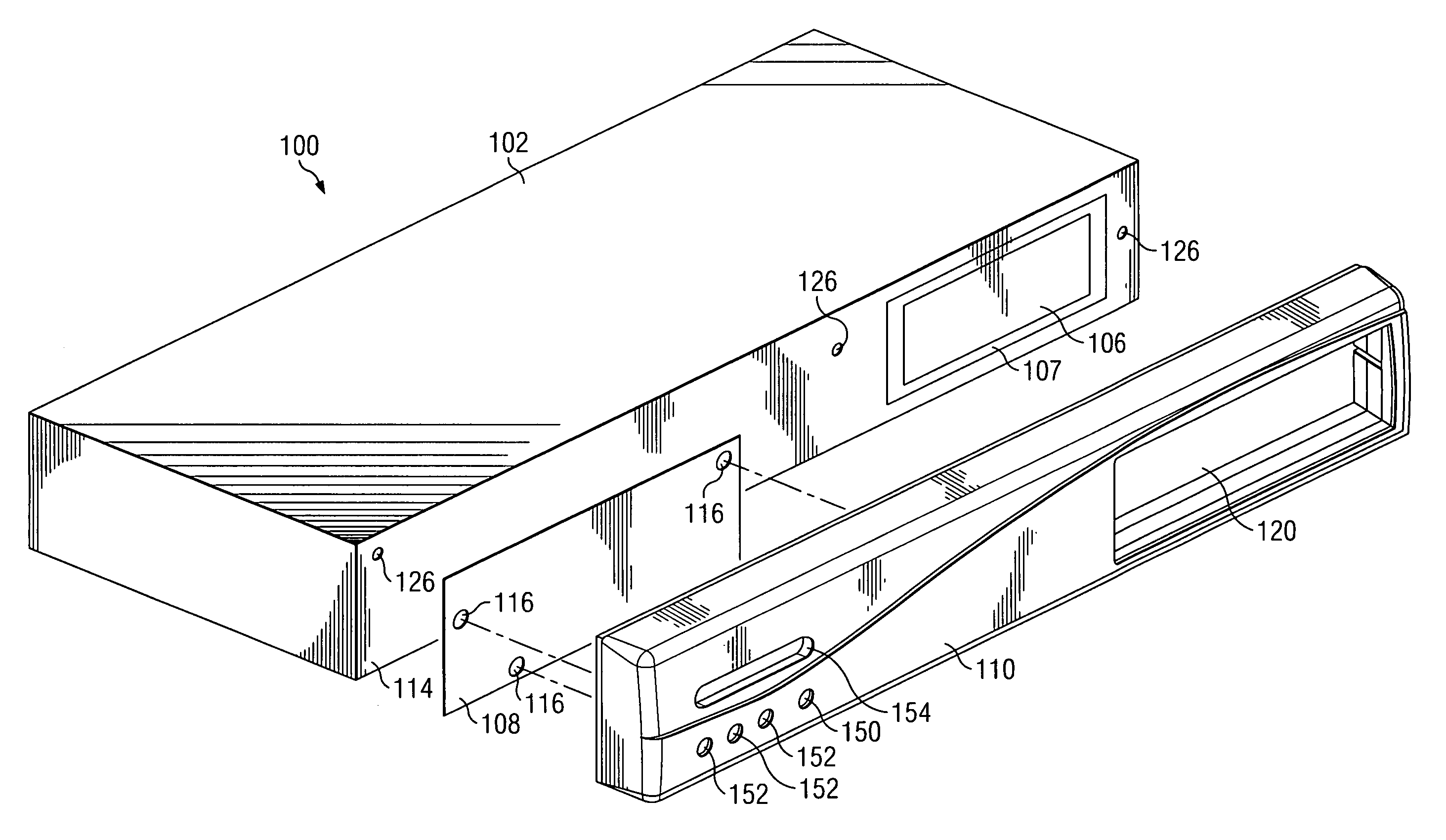
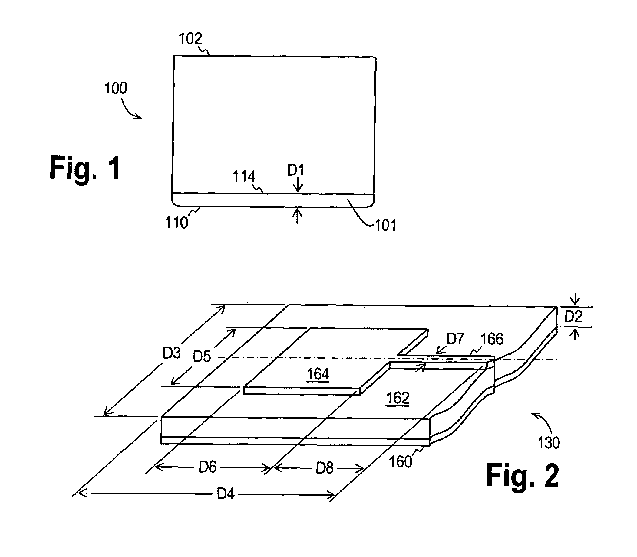
[0025]Referring now to FIG. 1, set top box 100 (shown in top view) as constructed in accordance with the preferred embodiment generally includes an enclosure 102 and a front bezel member 110. The set top box 100 may serve as not only a point of control for other devices as noted above, but may also serve as a host for other home entertainment components. The front bezel 110 defines an interstitial space 101 between the bezel and the front face 114 of enclosure 102. A distance D1 separates the bezel 110 from the front face 114. Various control components discussed below with respect to FIGS. 2–7 are located within interstitial space 101. Enclosure 102 in the preferred embodiment is manufactured from metal, preferably bent sheet aluminum, to shield electronics (...


PUM


Abstract

A set top box is provided with a patch antenna to wirelessly communicate with other devices. In one embodiment, the set top box has a metallic enclosure with a non-metallic bezel covering the front of the device. A communication circuit board with an imprinted patch antenna is located in the interstitial space between the metallic enclosure and the non-metallic bezel. The communications board preferably comprises a thin (0.06 inch) FR-4 circuit board with etched copper cladding. The patch antenna preferably comprises a ground plane on one side of the circuit board, and a rectangular patch on the opposite side of the circuit board. The patch is side-fed by a microstrip feed. The dimensions of the antenna are selected to optimize the antennas performance in frequency range between 2.400 and 2.483 GHz when located in the above-described interstitial space.

Description

CROSS-REFERENCE TO RELATED APPLICATIONS[0001]This application relates to U.S. Patent Application Ser. No. 09 / 685,506, entitled “Patch Antenna for a Set Top Box”, filed Oct. 10, 2000, which is now abandoned. This application is hereby incorporated herein by reference.BACKGROUND OF THE INVENTION[0002]1. Field of the Invention[0003]The present invention generally relates to a set-top box having an improved patch antenna. More particularly, the invention relates to a set-top box having an antenna provided on a front panel circuit board.[0004]2. Background of the Invention[0005]As consumers acquire more electronic devices they continually look for ways to integrate them into a single multifunctional system providing them with an efficient single point of control. Generally a single device lies at the nexus of an integrated system allowing each of the components to interface. One such device for allowing this kind of interfacing is known as a “set top box.” Typically, a set top box connec...

Claims


Application Information

Patent Timeline
Patent Type & Authority Patents(United States)
IPC IPC(8): H01Q1/24H01Q1/22H01Q9/04H04N7/16H04N7/20H04N21/41H04N21/426H04N21/4363
CPCH01Q1/22H01Q1/2266H01Q9/0407H04N21/43637H04N7/20H04N21/4126H04N21/426H04N7/16H04N21/41265
Inventor CUBLEY, H. DEANLIU, RICHARD C.
Owner EAGLE BROADBAND
Why Eureka
Try Eureka