
Antenna system of a radio communication terminal

a radio communication terminal and active antenna technology, applied in the field of radio communication terminals, can solve the problems of deteriorating speech quality, dipole antennas that are not suitable for fixed radio communication terminals, speech quality degradation, etc., and achieve the effect of improving speech quality

Inactive Publication Date: 2006-07-04
LG ELECTRONICS INC
View PDF17 Cites 2 Cited by
  • Summary
  • Abstract
  • Description
  • Claims
  • Application Information

AI Technical Summary

Benefits of technology

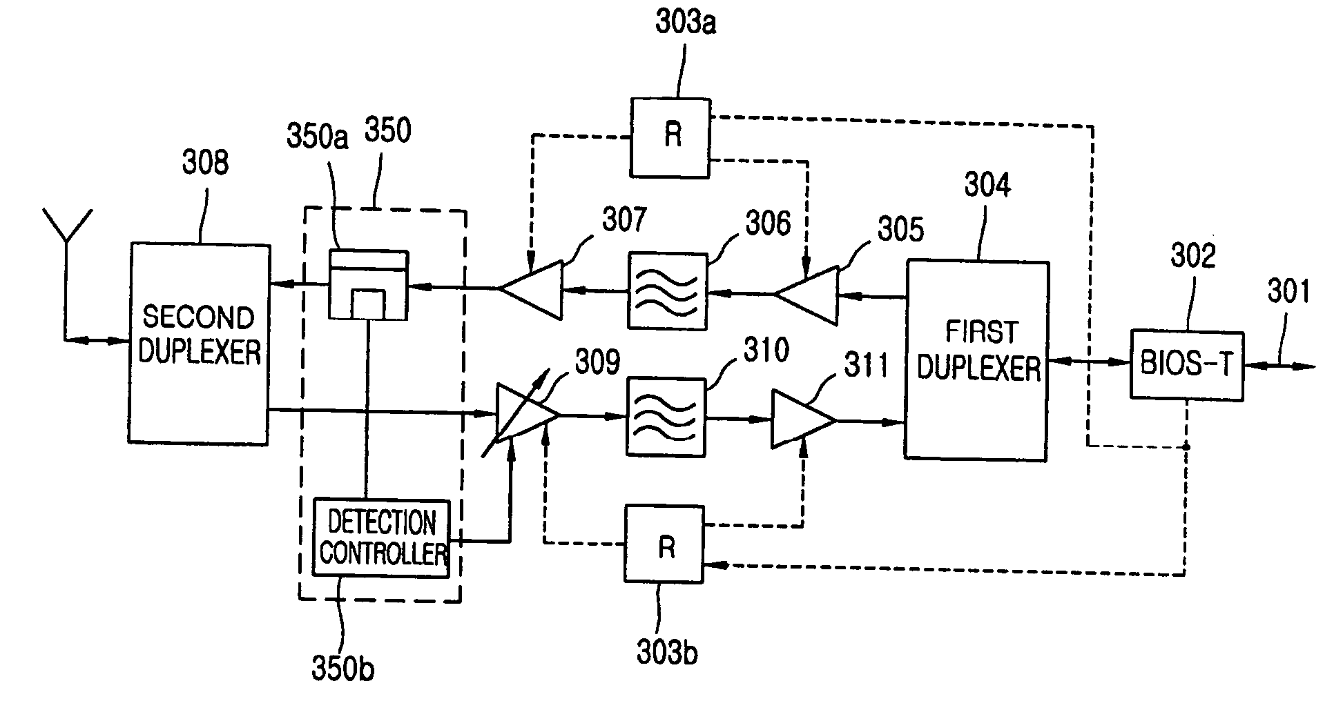
The present invention provides an active antenna system for a radio communication terminal that combines an antenna and an amplifying unit to enhance speech quality. It improves speech quality in areas where the radio environment is not good by improving transmission output and reception sensitivity. The system includes a directional antenna, a sending end amplifying / filtering unit, a receiving end amplifying / filtering unit, a closed loop control circuit, and a bias unit. The invention also provides a method for transmitting and receiving a communication signal in the antenna and amplifying and filtering it in the amplifying unit. The technical effects of the invention include improved speech quality, improved transmission and reception sensitivity, and improved communication quality.

Problems solved by technology

With such a low gain, the dipole antenna is not suitable for a fixed radio communication terminal.
However, the directional antenna has a problem that its speech quality is degraded due to losses generated and attributed to the transmission line.
In addition, although the directional antenna has a better direction property than that of the dipole antenna, its speech quality is deteriorated due to the loss generated at the transmission line.
Since the antenna characteristics are passive, there are limitations in improving the speech quality.

Method used


Image

  • Antenna system of a radio communication terminal
  • Antenna system of a radio communication terminal
  • Antenna system of a radio communication terminal

Examples


Embodiment Construction

[0026]An active antenna system of a radio communication terminal in accordance with various embodiments of the present invention will now be described with reference to the accompanying drawings.

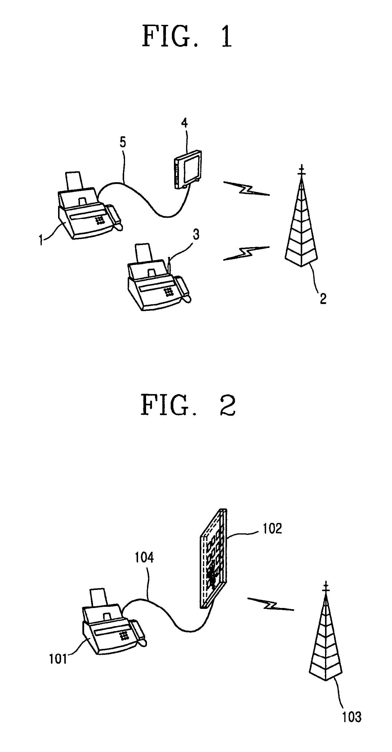
[0027]FIG. 2 illustrates a communication system of a radio communication terminal in accordance with the present invention. As shown in FIG. 2, an active antenna 102, a combination of a directional antenna and an amplifying unit, is connected to a fixed radio communication terminal 101 through a transmission line 104, and a radio communication link is formed between the active antenna 102 and a base station 103.

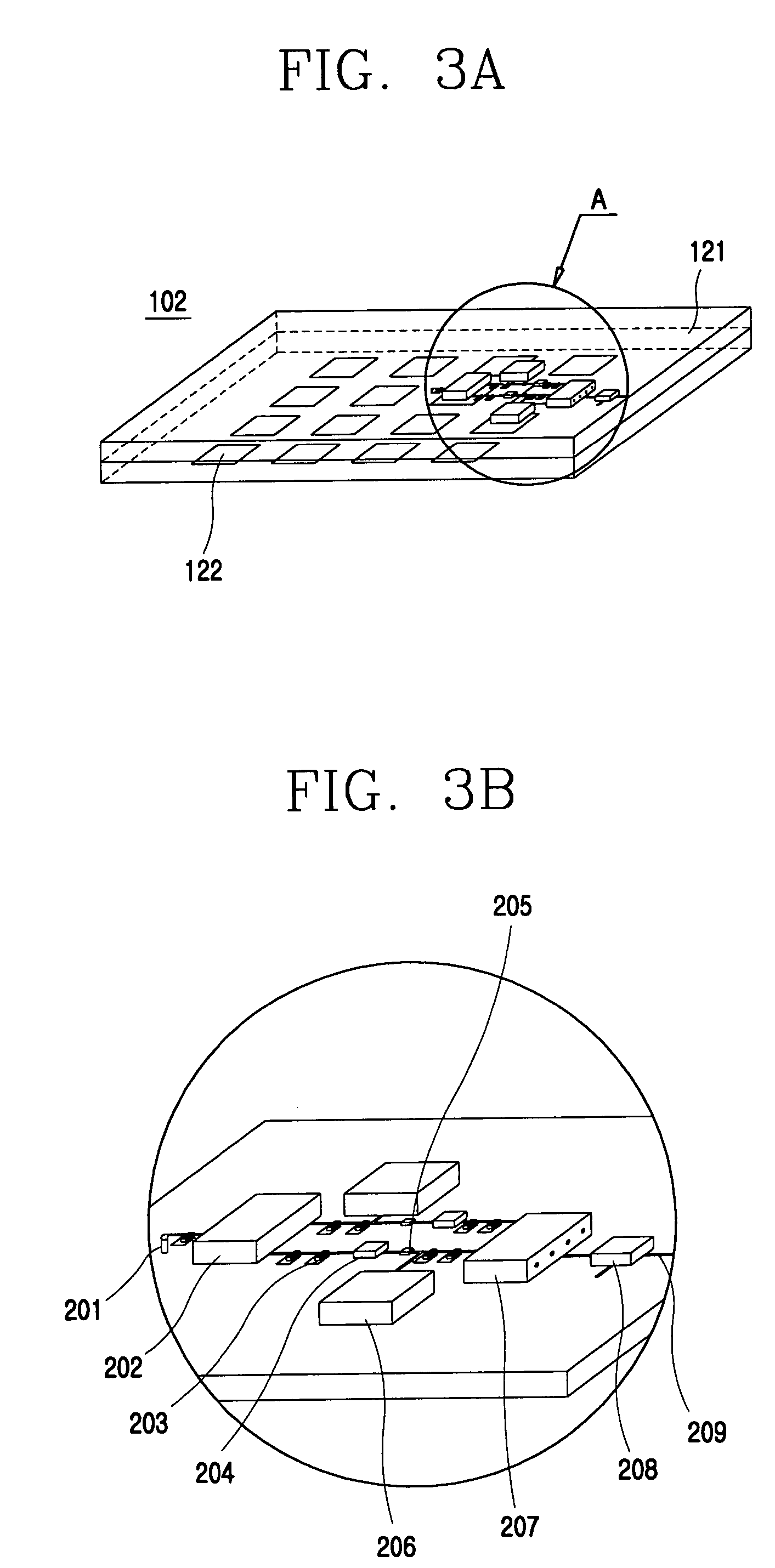
[0028]FIGS. 3A and 3B are detailed views of the active antenna system of the radio communication terminal as illustrated in FIG. 2, of which FIG. 3A is a perspective view showing an active antenna in accordance with the present invention and FIG. 3B is an enlarged view of a portion ‘A’ of FIG. 3A. In one embodiment, the present invention uses a micro strip patch array antenna among di...


PUM


Abstract

An antenna system of a radio communication terminal includes: a directional antenna for transmitting and receiving an RF signal to and from a base station through a radio link; and an amplifying unit integrated on one board together with the directional antenna and amplifying and filtering the RF signal. A transmistivity of a radio communication terminal is improved, a loss according to a transmission path between an antenna and the radio communication terminal can be compensated, and a speech quality can be maintained by above a certain level even in an area remote from a base station.

Description

BACKGROUND OF THE INVENTION[0001]1. Field of the Invention[0002]The present invention relates to a radio communication terminal and, more particularly, to an active antenna system of a radio communication terminal that is capable of improving a speech quality of a radio communication terminal in an area where a radio environment is degraded and speech quality is adversely affected.[0003]2. Background of the Related Art[0004]In general, a radio communication allows a terminal and a base station to exchange information such as a signal, a code, a voice, a data or the like through a radio link, for which a radio communication terminal converts data into a radio signal by using a transmission circuit and transmits it through an antenna and extracts an effective data from a radio signal received by the antenna by using a reception circuit.[0005]FIG. 1 illustrates a communication system of a radio communication terminal in accordance with the related art. As shown in FIG. 1, the related a...

Claims


Application Information

Patent Timeline
Patent Type & Authority Patents(United States)
IPC IPC(8): H01Q1/24H01Q17/00H04B17/00H01Q21/00H01Q21/06H01Q23/00
CPCH01Q21/0025H01Q23/00H01Q21/065H04B17/00
Inventor CHOI, TAE-KYU
Owner LG ELECTRONICS INC
Learn More