
Noise reduction method with self-controlling interference frequency

a noise reduction and frequency technology, applied in the direction of transducer casings/cabinets/supports, electrical transducers, instruments, etc., can solve the problems of limited maximum attainable noise reduction, difficulty in compensating for transient noise, and inability to be the case, etc., to achieve maximum effectiveness, good speech quality, and poor speech quality

Inactive Publication Date: 2006-03-28
CERENCE OPERATING CO +1
View PDF7 Cites 49 Cited by
  • Summary
  • Abstract
  • Description
  • Claims
  • Application Information

AI Technical Summary

Benefits of technology

[0014]An object of the present invention is to specify a noise reduction method which minimizes crosstalk of the useful signal into the interference reference signal.
[0022]The present invention has the advantage that markedly less useful signal components, such as speech components, are present in the interference reference signal than with the previous methods. It is thus possible for the interfering speech components to be eliminated under real conditions with speech signal reflections in real rooms as, for example, in the motor vehicle.
[0025]The ideal null for the speech signal in the reference is only achieved with an ideal spectral subtraction in the acoustic free-field. An ideal spectral subtraction produces the interference-suppressed speech signal as the output signal and would then eliminate the need for any further processing. In practice, spectral subtraction produces only a good approximation of the speech signal with residual noise during the speech pauses. Since the unilateral spectral subtraction is used in addition to the microphone null, the speech components of the reference are markedly reduced.
[0027]The maximum value for W is 1 (output=input). When the selection b=1 is made, the spectral subtraction is virtually switched off. With b=0, the spectral subtraction reaches maximum effectiveness. In practice, poor speech quality results when b=0. Parameter b makes it possible for the present invention to continuously adjust the unilateral spectral subtraction in its effectiveness. With a value of, for example, b=0.25, a noise suppression of about 12 dB and a good speech quality are achieved.

Problems solved by technology

A disadvantage consists in the signal delay (caused by the block processing in the spectral domain), the limited maximum attainable noise reduction, and the difficulty in compensating for transient noise.
In practical applications, however, this will not be the case.
In applications, however, no null is adjusted for the speech signal in the reference in spite of the sensitivity compensation with ‘gain’.
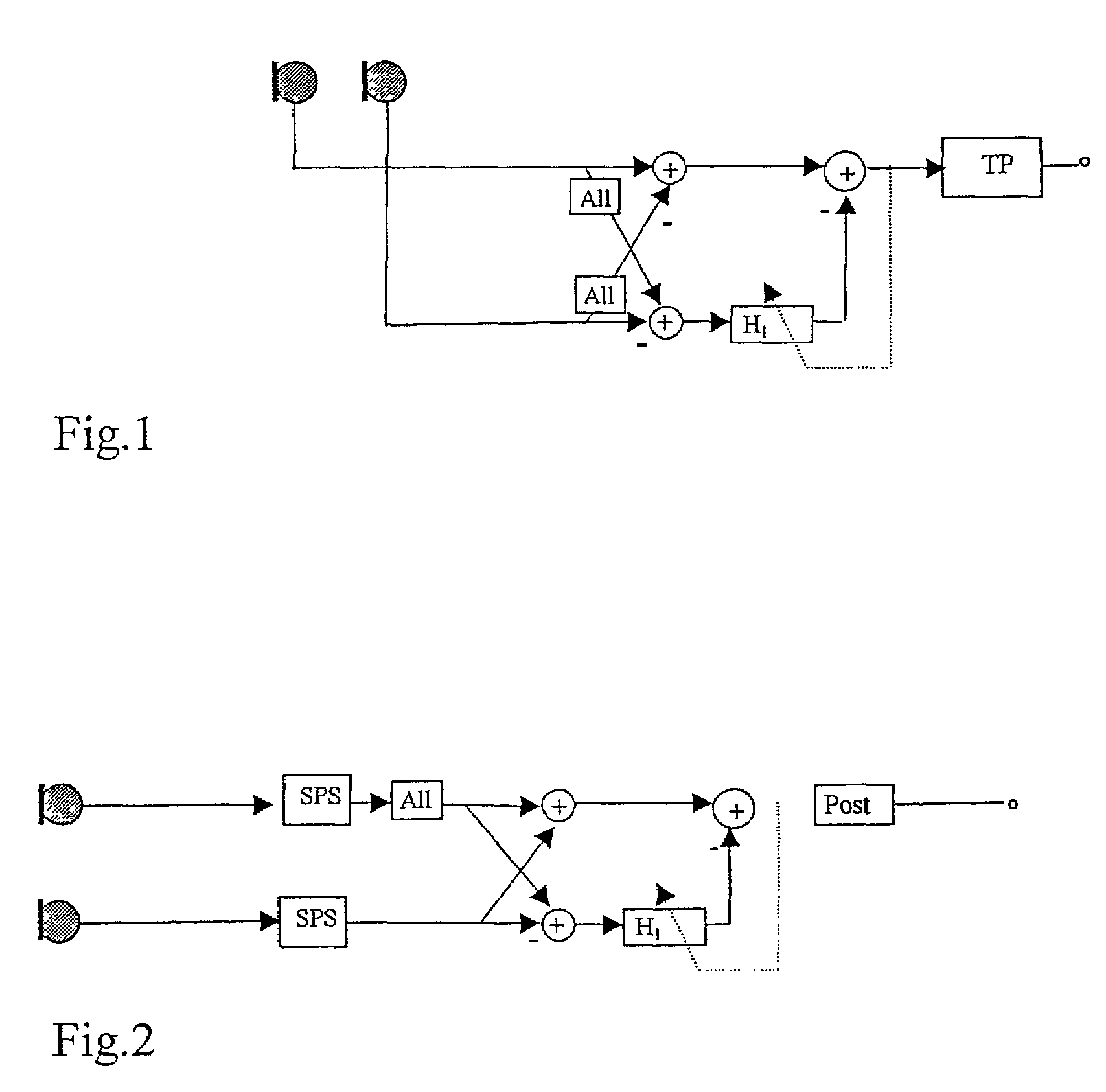
In the case of arrangements according to FIG. 1 or FIG. 2, a certain speech component will always be found in the reference signal of the beam former, resulting in speech distortions.

Method used


Image

  • Noise reduction method with self-controlling interference frequency
  • Noise reduction method with self-controlling interference frequency
  • Noise reduction method with self-controlling interference frequency

Examples


Embodiment Construction

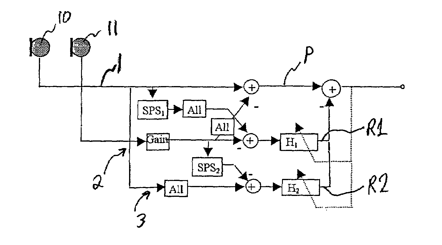
[0034]FIG. 4 shows 3 block diagrams with unilateral spectral subtraction for the reference input. The microphones 10, 11 are oriented to receive useful signals from the left in the figures.

[0035]In FIG. 4a, a primary signal P of the beam former (for example, a speech signal) is created using a differential array DA for channels 1, 2 (see arrangement c in FIG. 3), the microphones 10, 11 receiving the useful signals, for example a speech signal. FIGS. 4b and 4c show creating primary signal P as sum and difference array SD (see arrangements a and b in FIG. 3).

[0036]An interference reference input processes reference signal R with the additional extension of the unilateral spectral subtraction in differential form according to arrangements d and e in FIG. 3. The difference of the useful signal in channel 2 and the interference-suppressed useful signal from channel 1 is applied to adaptive filter H1. Adaptive filter H1 is adapted in the time domain or, in an equivalent form, in the frequ...


PUM


Abstract

The present invention relates to a method with which speech is captured in a noisy environment with as high a speech quality as possible. To this end, a compact array of, for example, two single microphones is combined to form one system through signal processing methods consisting of adaptive beam formation and spectral subtraction. Through the combination with a spectral subtraction, the reference signal of the beam former is freed from speech signal components to the extent that a reference signal of the interference is formed and the beam former produces high gains.

Description

[0001]Priority to German Patent Application No. 101 18 653.3-53, filed Apr. 14, 2001 and incorporated by reference herein, is claimed.BACKGROUND INFORMATION[0002]The present invention relates generally to a noise reduction method.[0003]A frequently used noise reduction method for a disturbed useful signal such as a voice signal, music signal, etc., is spectral subtraction. An advantage of spectral subtraction is the low complexity and that the disturbed useful signal is needed only in one variant (only one channel). A disadvantage consists in the signal delay (caused by the block processing in the spectral domain), the limited maximum attainable noise reduction, and the difficulty in compensating for transient noise. Stationary noise can be reduced, for example, by 12 dB, with the speech still having good quality.[0004]If a higher noise reduction or better speech quality are desired, several recording channels are required. One uses, for example, microphone arrays. Those of the diff...

Claims


Application Information

Patent Timeline
Patent Type & Authority Patents(United States)
IPC IPC(8): H04R3/00G10L21/0208G10L21/0216
CPCG10L21/0208G10L2021/02165
Inventor BUCK, MARKUSHAULICK, TIMLINHARD, KLAUS
Owner CERENCE OPERATING CO
Learn More