Plasma display panel and imaging device using the same

a technology of display panel and imaging device, which is applied in the direction of instruments, gas mixture absorption, and electrodes, etc., can solve the problems of unstable driving, and shortening the lifetime of the display device, so as to improve the luminous efficiency, long lifetime, and drive stably

Inactive Publication Date: 2006-07-04
MAXELL HLDG LTD
View PDF19 Cites 3 Cited by
  • Summary
  • Abstract
  • Description
  • Claims
  • Application Information

AI Technical Summary

Benefits of technology

[0007]The present invention provides a PDP capable of improving luminous efficiency, guaranteeing long lifetime, and being driven stably. Further, the PDP in accordance with the present invention makes possible a high-brightness, high-definition and low-price display device.
[0008]To solve the above problems, the features of the present invention include selection of the composition and total pressure of the discharge gas, the pulse width of a write voltage and so forth. Such features contribute to the improved luminous efficiency, guaranteed long lifetime, and elimination of instability in driving.
[0015]In a third embodiment of the present invention, a discharge-gas mixture contains a Xe proportion in a range of from 6% to 14% and a He proportion in a range of from 15% to 50% with the He proportion being greater than the Xe proportion; a total pressure of the discharge-gas mixture is in a range of from 400 Torr to 550 Torr; and a width of voltage pulses to be applied to address electrodes is 2 μs or less. This embodiment realizes a PDP which provides particularly high brightness and excellent luminous efficiency.
[0016]In a fourth embodiment of the present invention, a discharge-gas mixture contains a Xe proportion in a range of from 6% to 12% and a He proportion in a range of from 15% to 50% with the He proportion being greater than the Xe proportion; a total pressure of the discharge-gas mixture is in a range of from 400 Torr to 550 Torr; and a width of voltage pulses to be applied to address electrodes is 2 μs or less. Advantages achieved by the He proportion is particularly pronounced for the above Xe proportion, and the luminous efficiency is improved effectively to realize a high-brightness PDP.

Problems solved by technology

However, there is a problem in that an excessive amount of He shortens lifetime of the display device.
When the composition and pressure of the discharge gas are changed to improve the luminous efficiency, lifetime may be shortened, and driving may be unstable.

Method used


Image

  • Plasma display panel and imaging device using the same
  • Plasma display panel and imaging device using the same
  • Plasma display panel and imaging device using the same

Examples


Embodiment Construction

Basic Structure and Operation

[0032]An ac coplanar-discharge type PDP is an imaging device having a large number of small discharge spaces (discharge cells) sealed between a pair of glass substrates.

[0033]The embodiments will be explained with reference to the accompanying drawings. The same reference numerals designate corresponding or functionally similar parts or portions throughout the figures, and repetition of their explanations is omitted.

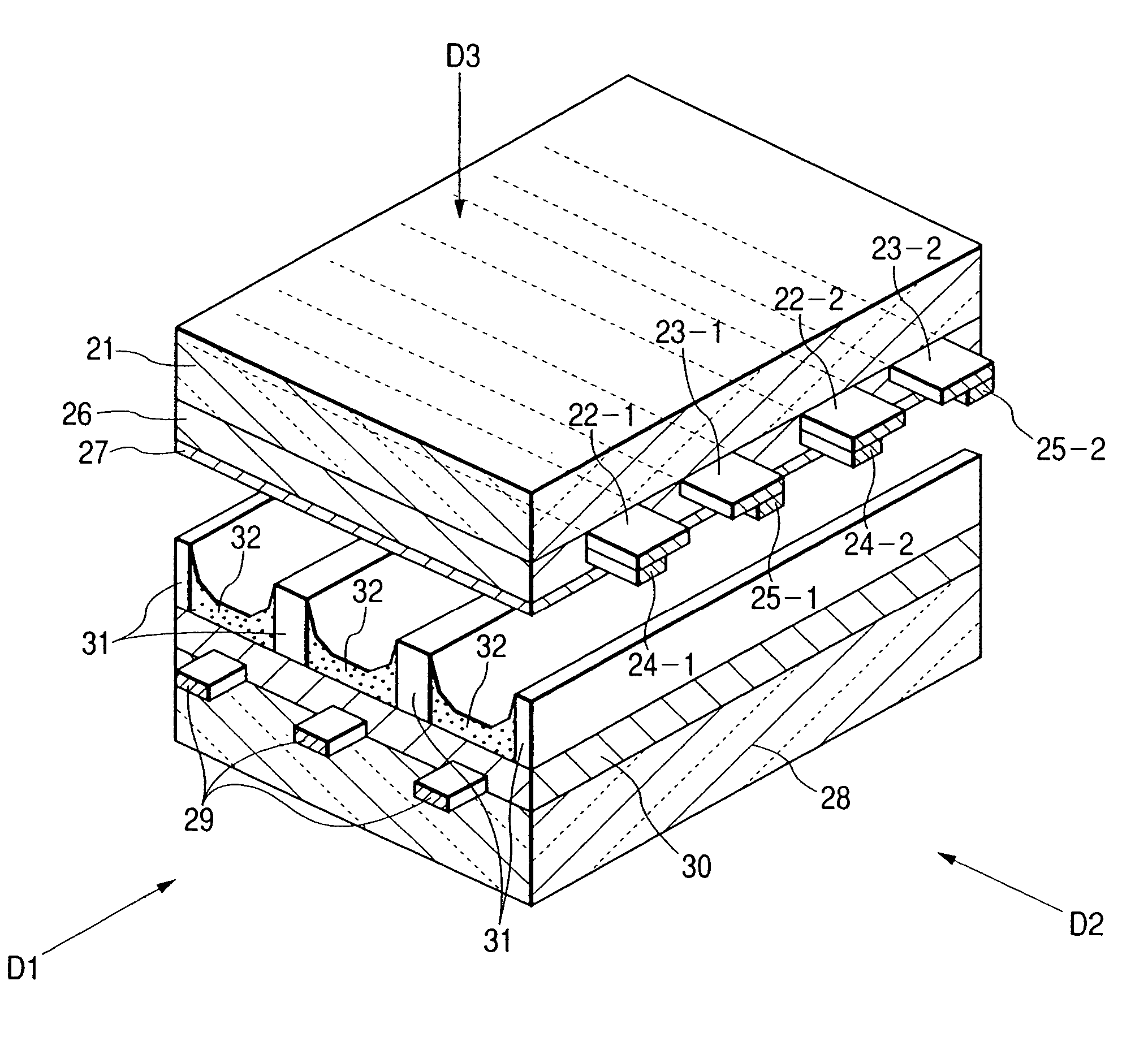
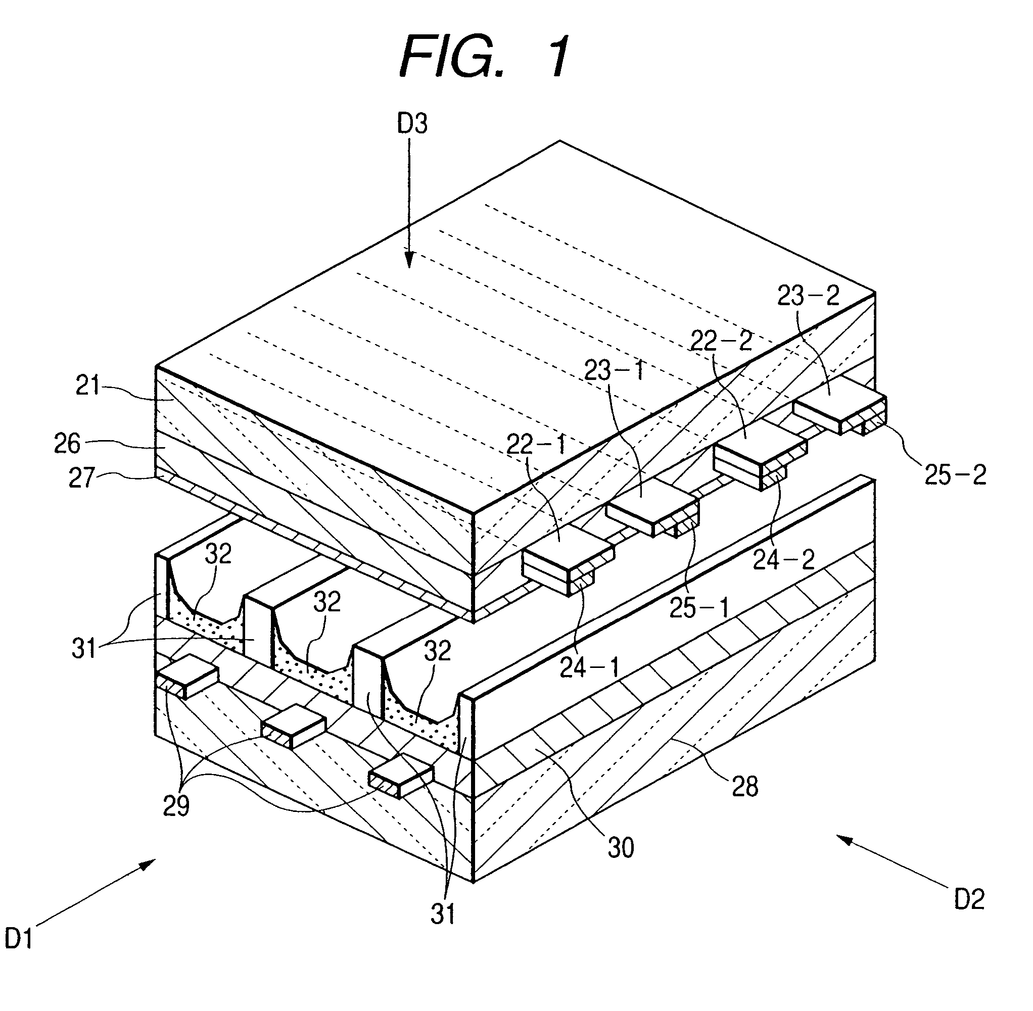
[0034]FIG. 1 is an exploded perspective view illustrating a part of a structure of a typical ac coplanar-discharge type PDP by way of example. The PDP shown in FIG. 1 has a front panel 21 and a rear panel 28 which are made of glass and affixed together in an integrated manner. The present example is a reflection type PDP in which phosphor layers 32 of red (R)-, green (G)-, and blue (B)-color phosphors are formed on the rear panel 28. The front panel 21 has a plurality of pairs of sustaining discharge electrodes (sometimes referred to as “disp...


PUM


Abstract

A plasma display panel and an imaging device realize a high luminous efficiency, a long lifetime and stable driving. The plasma display panel uses a discharge-gas mixture containing at least Xe, Ne and He. A Xe proportion of the discharge-gas mixture is in a range of from 2% to 20%, a He proportion of the discharge-gas mixture is in a range of from 15% to 50%, the He proportion is greater than the Xe proportion, and a total pressure of the discharge-gas mixture is in a range of from 400 Torr to 550 Torr. A width of a voltage pulse to be applied to an electrode serving as an address electrode is 2 μs or less.

Description

CROSS-REFERENCE TO RELATED APPLICATION[0001]This application is a continuation of application Ser. No. 10 / 222,583 filed Aug. 19, 2002 (now U.S. Pat. No. 6,822,627 issued Nov. 23, 2004).FIELD OF THE INVENTION[0002]The present invention relates to a plasma display panel and an imaging device using the same.BACKGROUND OF THE INVENTION[0003]In recent years, plasma display panels (hereinafter referred to as “PDPs”) have attracted considerable attention as large- and flat-screen and low-profile display devices. At the present, ac-drive coplanar-discharge type PDPs (hereinafter referred to as “ac coplanar-discharge type PDPs”) are dominant. The ac coplanar-discharge type PDP is an imaging device having a large number of small discharge spaces (discharge cells) sealed between a pair of glass substrates.[0004]In the PDP, plasma is created by discharge of gases (discharge gases) contained in the discharge cells, and ultraviolet rays from the plasma excite phosphors to emit visible light and t...

Claims


Application Information

Patent Timeline
Patent Type & Authority Patents(United States)
IPC IPC(8): G09G3/28H01J11/52G09G3/20G09G3/288G09G3/291G09G3/293G09G3/296G09G3/298H01J11/12H01J11/14H01J11/24H01J11/26H01J11/50H01J17/20
CPCG09G3/2022G09G3/288G09G3/293H01J11/50H01J11/12G09G3/294G09G2320/02G09G3/296H01J11/52
Inventor UEMURA, NORIHIROSUZUKI, KEIZOKAJIYAMA, HIROSHIYAJIMA, YUSUKESHIBATA, MASAYUKIKAWANAMI, YOSHIMIOHIRA, KOJIOZAKI, IKUO
Owner MAXELL HLDG LTD
Why Eureka
Try Eureka