Microscope with objective lens position control apparatus

a position control apparatus and microscope technology, applied in the field of microscopes, can solve the problems of inability to transport liquid, inability to carry a liquid, and inability to perform field visits to a distant location, so as to increase the sensitivity of specimen observation, facilitate transportation, and facilitate the effect of portable microscopes

Inactive Publication Date: 2006-07-04
MONTEREY RES LLC
View PDF18 Cites 11 Cited by
  • Summary
  • Abstract
  • Description
  • Claims
  • Application Information

AI Technical Summary

Benefits of technology

[0008]According to the invention, a microscope can be constructed that has one or more advantageous characteristics as compared to previous microscopes. The invention enables construction of a small and lightweight microscope by, for example, implementing aspects of microscope functionality in smaller and lighter apparatus than that used in previous microscopes, combining multiple aspects of microscope functionality into a single apparatus, and eliminating apparatus found in previous microscopes. In particular, the invention enables construction of a microscope for use in microscopic liquid crystal analysis of semiconductor devices that is smaller and far lighter than microscopes (e.g., probe station microscopes) previously used for such analysis. For example, a microscope according to the invention can include a lightweight bellows that provides zoom capability (in particular, the bellows can be much lighter than the structure provided to produce zoom capability in microscopes previously used for microscopic liquid crystal analysis of semiconductor devices). Further, the light weight and small size of a microscope according to the invention advantageously enables the microscope to be portable. In particular, a microscope according to the invention can be made sufficiently small and lightweight to enable the microscope to be easily transported to a location of a specimen to be observed with the microscope. This can advantageously enable the specimen to be observed with the microscope while the specimen is positioned in the environment in which the specimen normally exists (e.g., to analyze operation of a semiconductor chip connected to a printed circuit board with other electronic components). Another advantageous characteristic of the invention is that a microscope according to the invention and/or a tripod that is used with the microscope can be implemented to provide objective lens position control capability (with any number of translational and/or rotational degrees of freedom). Consequently, it is not necessary to provide a movable stage for mounting the specimen, since the objective lens can be moved to achieve a desired relative position of the specimen and objective lens. This aspect of the invention also enables a specimen to be observed while positioned in the environment in which the specimen normally exists, since the specimen need not be mounted on a movable stage. A microscope according to the invention can also include apparatus for ejecting a temperature-controlled gas (heated gas or refrigerated gas) from the microscope to control the temperature of a specimen being observed with the microscope. This can advantageously increase the sensitivity of observation of the specimen. This can also advantageously inhibit impairment of the analysis that would otherwise occur without controlling the temperature of the specimen.
[0009]In one embodiment of the invention, a microscope includes: 1) an objective lens positioned proximate to a specimen, 2) optical apparatus for transmitting light to the specimen and for transmitting light reflected from the specimen through the objective lens, 3) viewing apparatus for viewing a magnified image of the specimen produced from the reflected light, and 4) a bellows positioned between the objective lens and an image formation plane of the viewing apparatus. At least one of the objective lens and the image formation plane of the viewing apparatus is movable in response to expansion or contraction of the bellows to vary the distance between the objective lens and the image formation plane of the viewing apparatus and thereby change the magnification of the magnified image. The bellows advantageously provides zoom capability using small and lightweight apparatus. The small and lightweight bellows can also eliminate the need to provide a heavy microscope body. A microscope according to this embodiment of the invention can further include bellows control apparatus for effecting expansion or contraction of the bellows. The bellows control apparatus can be implemented by 1) a bellows slide attached to a first end of the bellows, 2) a bellows slide bar which remains fixed in position relative to a second end of the bellows opposite the first end of the bellows, and 3) a bellows slide location control knob that can be moved to move the bellows slide along the bellows slide bar to expand or contract the bellows. The viewing apparatus can be implemented by a visual image data acquisition apparatus (e.g., a video camera) and can further include a display device operably connected to the visual image data acquisition apparatus to enable data acquired by the visual image data acquisition apparatus to be transmitted to the display device for generation of a display of the magnified image of the specimen. The viewing apparatus can also be implemented by an eyepiece. The microscope can include multiple objective lenses which can be formed on, or attached to, a rotatable turret. The optical apparatus can be implemented by a light source and a b...

Problems solved by technology

The microscopes previously used for microscopic liquid crystal analysis of semiconductor devices cannot be moved easily or at all.
For example, it is typically not feasible to transport a liquid crystal analysis microscope to a location that is geographically remote from that at which the microscope is usually located (because, for example, such microscopes are too large and heavy to be transported as luggage on a commercial airliner), making a field visit to a distant location impractical.
Even when it is possible to move a liquid crystal analysis microscope, special equipment and/or packaging is required to transport the microscope, making transportation of the microscope unduly expensive and time consuming.
This can be disadvantageous.
Analyzing a semiconductor device apart from a system of which the semiconductor device is part may result in an inability to reproduce a problem that instigated the analysis of the semiconductor device and/or may inhibit the ability to test solutions to problems with operation of the semiconductor device.
Additionally, transporting a semiconductor device to the location of an analysis microscope may be inconvenient, impractical, unduly time consuming and/or impossible...

Method used


Image

  • Microscope with objective lens position control apparatus
  • Microscope with objective lens position control apparatus
  • Microscope with objective lens position control apparatus

Examples


Embodiment Construction

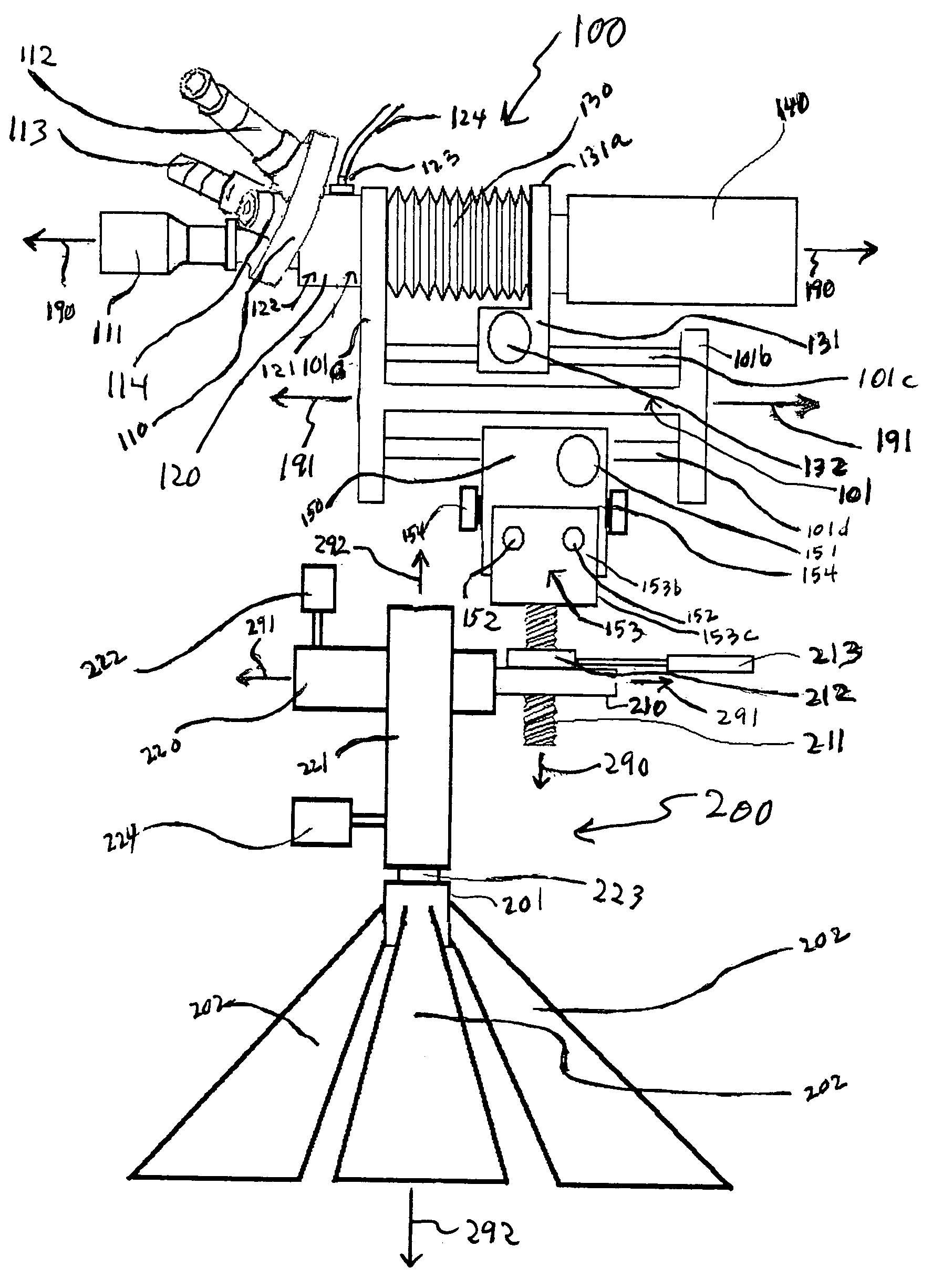
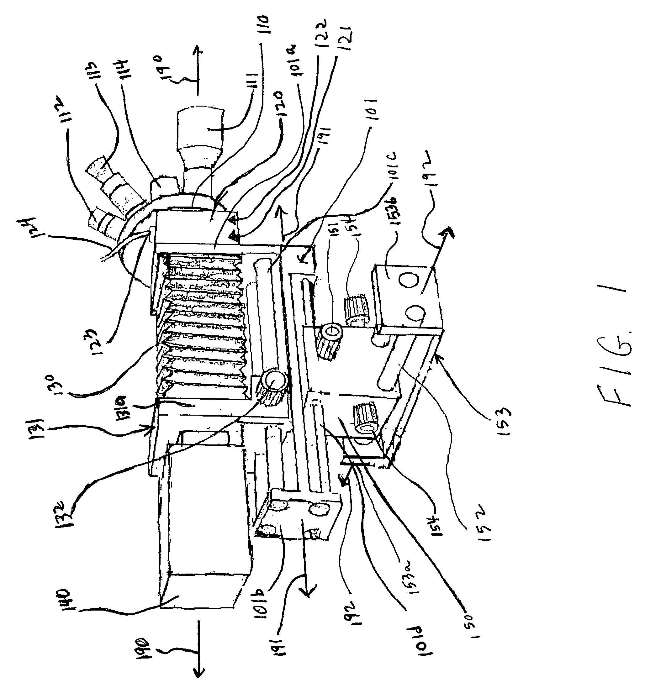
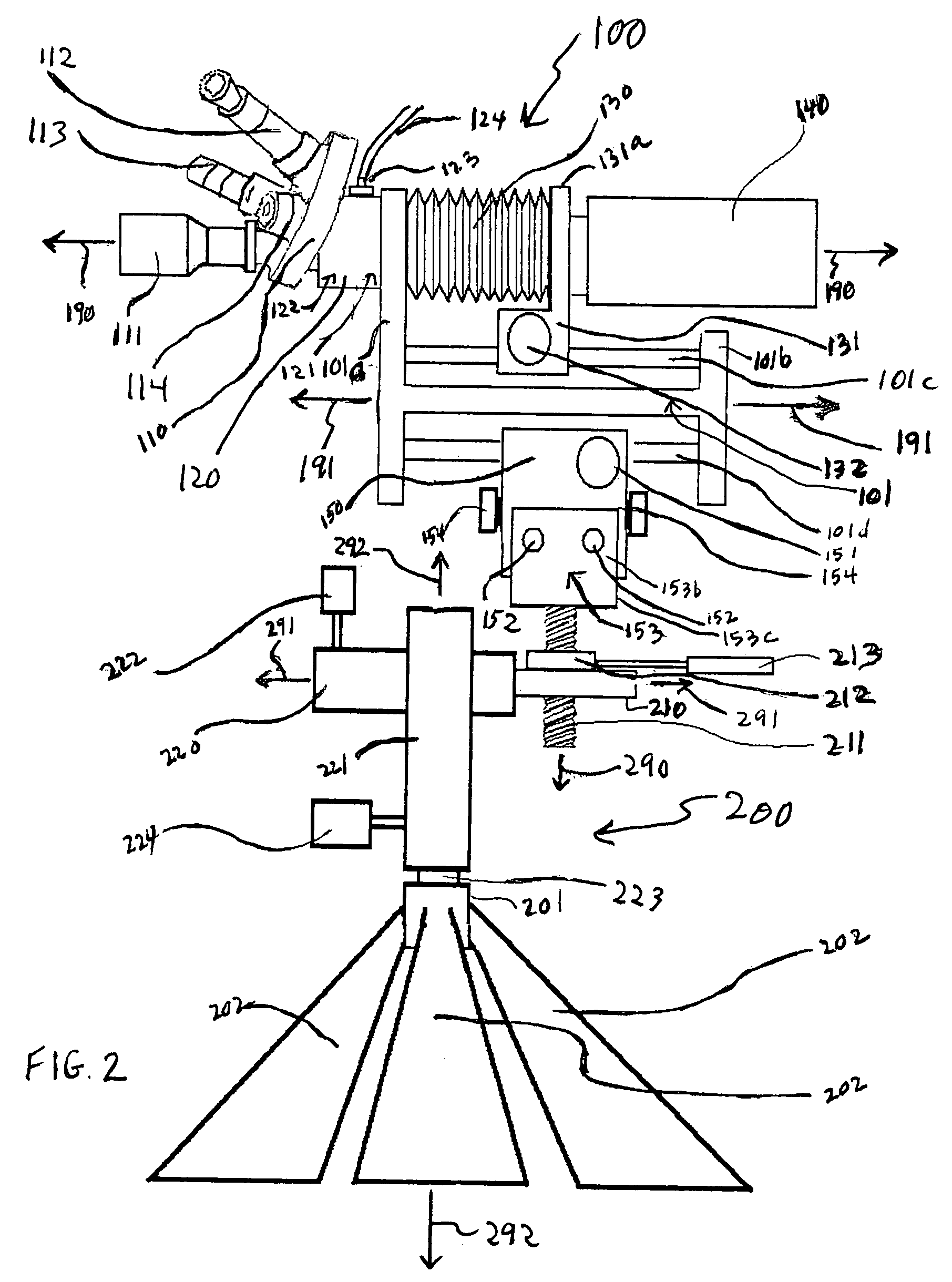
[0018]FIG. 1 is a perspective view of a microscope 100 according to an embodiment of the invention. Four objective lenses 111, 112, 113 and 114 are mounted on a turret 110. Though the microscope 100 illustrated in FIG. 1 (and FIG. 2, described below) includes four objective lenses, generally a microscope according to the invention can include any number of objective lenses (i.e., one, two or more objective lenses). An objective lens of a microscope according to the invention can be attached to a turret (or other support structure) of the microscope using any of a variety of appropriate techniques and / or apparatus, as can be readily appreciated by those skilled in the art. For example, an objective lens of a microscope according to the invention can be constructed with a base having a threaded section that screws into a corresponding threaded hole of a turret or other support structure of the microscope (see, e.g., the objective lens 500 illustrated in FIG. 5 and described below). In...


PUM


Abstract

The invention enables construction of a microscope that has one or more advantageous characteristics as compared to previous microscopes. The microscope can be small and lightweight and, in particular, sufficiently small and light weight to be portable (e.g., smaller and far lighter than probe station microscopes used for microscopic liquid crystal analysis of a semiconductor device). The microscope can include a small and lightweight bellows that provides zoom capability. The microscope and/or a tripod that is used with the microscope can be implemented to provide objective lens position control capability (with any number of translational and/or rotational degrees of freedom). The microscope can include apparatus for ejecting a hot gas from the microscope to heat a specimen being observed with the microscope.

Description

BACKGROUND OF THE INVENTION[0001]1. Field of the Invention[0002]This invention relates to a microscope and, in particular, to a zoom capability, specimen heating capability and objective lens positioning capability of a microscope. The invention further relates to the use of a microscope for liquid crystal analysis of a semiconductor device and, in particular, to a microscope for such use that is portable.[0003]2. Related Art[0004]Microscopic liquid crystal analysis is sometimes used to perform failure analysis of semiconductor devices. Previously, microscopic liquid crystal analysis of semiconductor devices has been performed using large, bulky, heavy microscopes. For example, large probe station microscopes (such as made by SUSS MicroTec, located in Waterbury, Vt. and headquartered in Munich, Germany, or by Signatone Corporation located in Gilroy, Calif.) that have been used for microscopic liquid crystal analysis of semiconductor devices have weighted between 500 and 1500 pounds....

Claims


Application Information

Patent Timeline
IPC IPC(8): G02B21/00
CPCG02B21/0016G02B21/30G02B21/248
Inventor ATCHISON, NICKEY JOE
Owner MONTEREY RES LLC
Why Eureka
Try Eureka