Method of firing a paintball marker

a paintball marker and firing method technology, applied in the field of grip frames, to achieve the effect of increasing the firing rate of the marker and the higher fire ra

Inactive Publication Date: 2006-07-11
PLANET ECLIPSE
View PDF15 Cites 24 Cited by
  • Summary
  • Abstract
  • Description
  • Claims
  • Application Information

AI Technical Summary

Benefits of technology

[0006]The electro-pneumatic paintball marker of the present invention has a much higher rate of fire than a mechanically operated paintball marker and this is a major advantage in modern paintball. The grip frame of the invention is intended for fitting onto a mechanically operated paintball marker in order to convert that marker into an electro-pneumatic marker and thus increase the rate of fire of the marker. The inventive grip frame replaces the entire grip frame of an existing paintball marker along with the hammer release mechanism and the mechanically operated pneumatic valve.
[0009]Specifically the breech sensor is used to detect the presence of objects at a position in the breech below the feed aperture through which the paintballs enter the breech. This sensor is used to detect that a paintball is in the breech before the bolt can travel forwards thus preventing the bolt from breaking a ball that has not completely passed through the feed aperture, a major problem when trying to operate other paintball markers at high rates of fire. The sensor is also used to detect that the bolt is fully forwards prior to the marker being fired, thus preventing gas from escaping the breech through the feed aperture and ensuring maximum gas efficiency.
[0010]As the trigger does not operate an electrical switch, as in the case in other paintball markers, but senses the movement of the trigger by means of a sensor, moving parts are reduced which makes the marker more reliable than other paintball markers.
[0012]The LED display provides improved viewing in low light conditions over the LCD displays used on other paintball markers. Mounting the display at the rear of the grip frame allows the user to view the display without having to move the paintball marker from its shooting position. This is an improvement over the other paintball markers where displays are mounted on either the side of the marker or the side of the grip frame.

Problems solved by technology

This sensor is used to detect that a paintball is in the breech before the bolt can travel forwards thus preventing the bolt from breaking a ball that has not completely passed through the feed aperture, a major problem when trying to operate other paintball markers at high rates of fire.

Method used


Image

  • Method of firing a paintball marker
  • Method of firing a paintball marker
  • Method of firing a paintball marker

Examples


Embodiment Construction

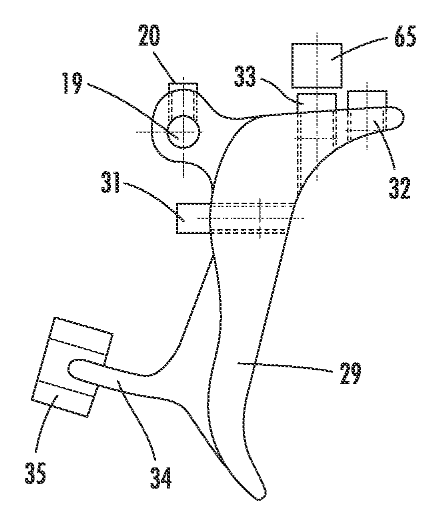
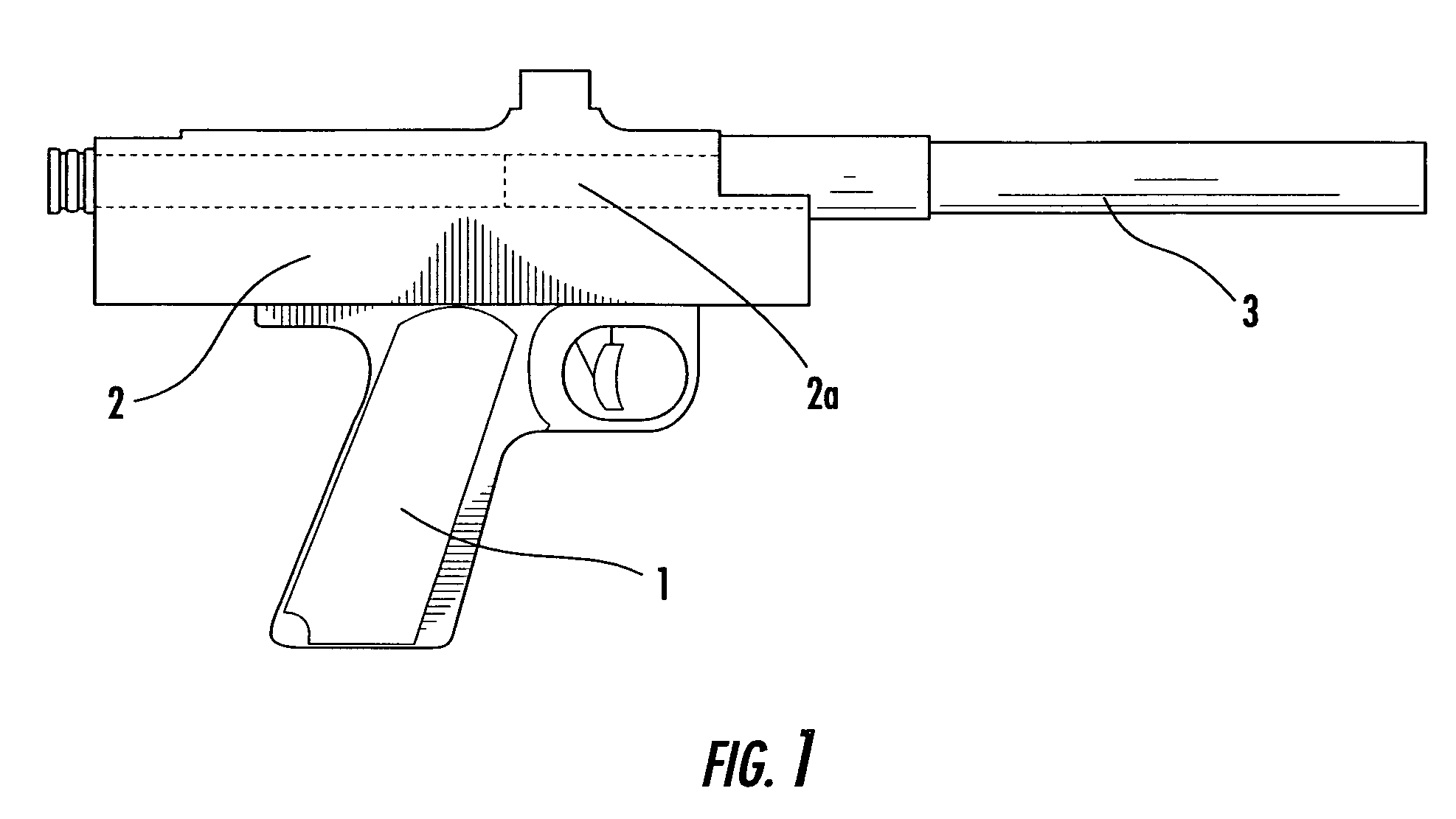
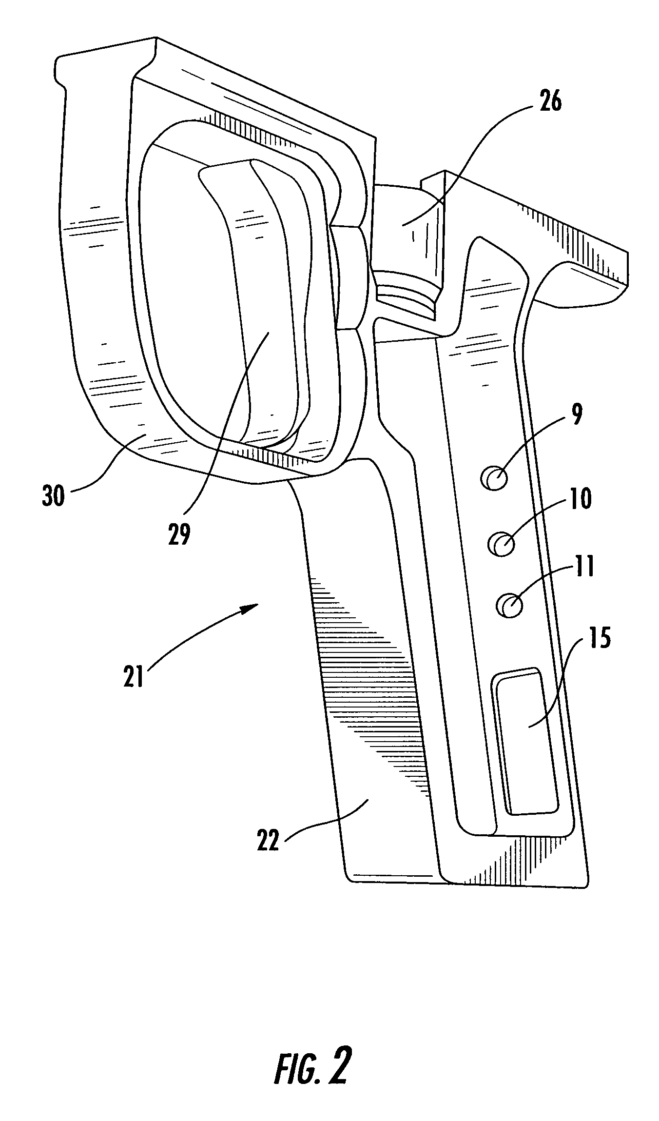
[0027]Referring to FIG. 1, the mechanically operated paintball marker comprises a grip frame 1 firing mechanism comprising body 2 defining a breech 2a and barrel 3. Referring to FIGS. 2, 3a 3b and 3c, an electronic grip frame 21 to replace the mechanical grip frame 1 is shown. Grip frame 21 comprises a handle 22 defining a cavity 23 in which an electronic circuit board 24 and an electrical battery 25 are located. Above this cavity 23 is a second cavity in which a hammer release assembly comprising a sear solenoid 26, pin 28 and sear 27 is disposed. This hammer release assembly is controlled by a trigger 29 which is protected by a trigger guard 30 to reduce the possibility of accidental operation. The hammer release assembly will be described in more detail later with reference to FIG. 6.

[0028]The trigger 29 can be operated by either one or two fingers, the trigger guard 30 being large enough to accommodate two fingered operation. At the rear of the grip frame three recessed holes 9,...


PUM


Abstract

The method of firing a paintball marker uses a grip frame 21 replaces an existing grip frame 1 on a paintball marker in order to convert said paintball marker from a mechanically operated paintball marker into an electro-pneumatic paintball marker. The electronic grip frame 21 utilises an optical sensor in order to detect the operation of a trigger 29 and a second optical sensor to detect the presence of objects within the breech of the paintball marker. Electrical signals from these sensors are taken to an electronic circuit board 24, which controls the operation of two solenoids (one shown 26) in order to fire and re-cock the paintball marker. A user interface comprising pushbuttons 12, 13, 14 and a multi-character display 16, allows the user to define how the grip frame 21 functions.

Description

CROSS-REFERENCE TO RELATED APPLICATIONS[0001]This application is a divisional of U.S. Ser. No. 10 / 604,444, filed on Jul. 22, 2003, which claims the benefit of U.K. Patent Application Serial No. 0217099.1, filed on Jul. 24, 2002.BACKGROUND OF THE INVENTION[0002]This invention relates to a grip frame. The frame is intended to form an integral part of a paintball marker and to be supplied as an upgrade for existing paintball markers.[0003]A paintball marker, also known as a paintball gun or paintball launcher, is a device used to propel paintballs. A paintball is a spherical object typically 0.68 inch diameter, comprised of a fragile shell which encapsulates a coloured liquid. When a paintball that has been launched from a paintball marker comes into contact with a hard surface, the shell of the paintball ruptures and the coloured liquid is released, leaving a bright mark on the surface.[0004]One type of paintball marker is a mechanically operated marker. With this type of marker the u...

Claims


Application Information

Patent Timeline
Patent Type & Authority Patents(United States)
IPC IPC(8): F41A19/00F41A19/10F41A19/69F41B11/57
CPCF41A19/10F41B11/57F41A19/69
Inventor MONKS, STEVEN JOHNWOOD, JACK KINGSLEY
Owner PLANET ECLIPSE
Why Eureka
Try Eureka