Jacking frame for coiled tubing operations

a technology of coiled tubing and jacking frame, which is applied in the field of modular systems, can solve the problems of complicated rig up process, low utilization rate of pressure control equipment in offshore environments, and inability to integrate pressure control equipment, so as to improve safety and the working environment, improve the utilization rate, and improve the time and safety.

Inactive Publication Date: 2006-07-11
SCHLUMBERGER TECH CORP
View PDF36 Cites 47 Cited by
  • Summary
  • Abstract
  • Description
  • Claims
  • Application Information

AI Technical Summary

Benefits of technology

[0012]The subject invention is directed to a modular, pre-assembled system for rig workovers, and a preferred embodiment is a modular, pre-assembled system specifically designed for coiled tubing operations. The system of the subject invention results in improved equipment utilization and in significant improvements in time, personnel and safety issues. The system also improves safety and the working environment by minimizing Rig Up time through the ability to pre-assemble many critical safety components off rig and in a controlled factory environment.
[0013]One important aspect of the invention is that the use of pre-assembled modular components decreases or reduces use of the rig crane, which is typically a bottleneck in offshore work. By permitting a plurality of pre-assembled components to be transported into and out of operational position, the time required by the rig crane is substantially reduced.
[0014]Specifically, the subject invention is directed to a modular work system permitting Rig Up time to be substantially reduced by reducing the number of crane lifts and number of personnel required to offload equipment from a transport boat or other transport vehicle. This is achieved by developing transport skids capable of holding multiple system components. The invention is also directed to reducing the number of crane lifts required to position equipment on the platform. One objective of the present invention to reduce the number of equipment components that must be mechanically coupled on location by pre-assembling the components and maintaining the assembly in operating condition during storage and transport. This pre-assembly also applies to hydraulic and other control lines. An additional advantage of the system of the subject invention is the reduction of personnel time and numbers required to support the operation on the rig.

Problems solved by technology

The deployment of coiled tubing pressure control and conveyance equipment in offshore environments is a time consuming process made complicated by spatial constraints, crane lifting limitations, safety considerations and intensive assembly on location.
The majority of coiled tubing systems utilized offshore to date incorporate virtually no pre-assembly of system components making the Rig Up process extremely inefficient.
Very little integration of conveyance and pressure control equipment is currently utilized offshore.
The principal hindrance in the Rig Up of existing coiled tubing systems is the need to assemble virtually every component in the system on location.
This fragmentation of the operation results in numerous crane lifts to move equipment components into position and numerous assembly steps to couple these components together.
A major drawback to pre-rigging or assembly prior to Rig Up is the sheer size of the equipment being utilized.
To date, there are not any available systems that permit comprehensive pre-rigging at an offsite location.

Method used


Image

  • Jacking frame for coiled tubing operations
  • Jacking frame for coiled tubing operations
  • Jacking frame for coiled tubing operations

Examples


Embodiment Construction

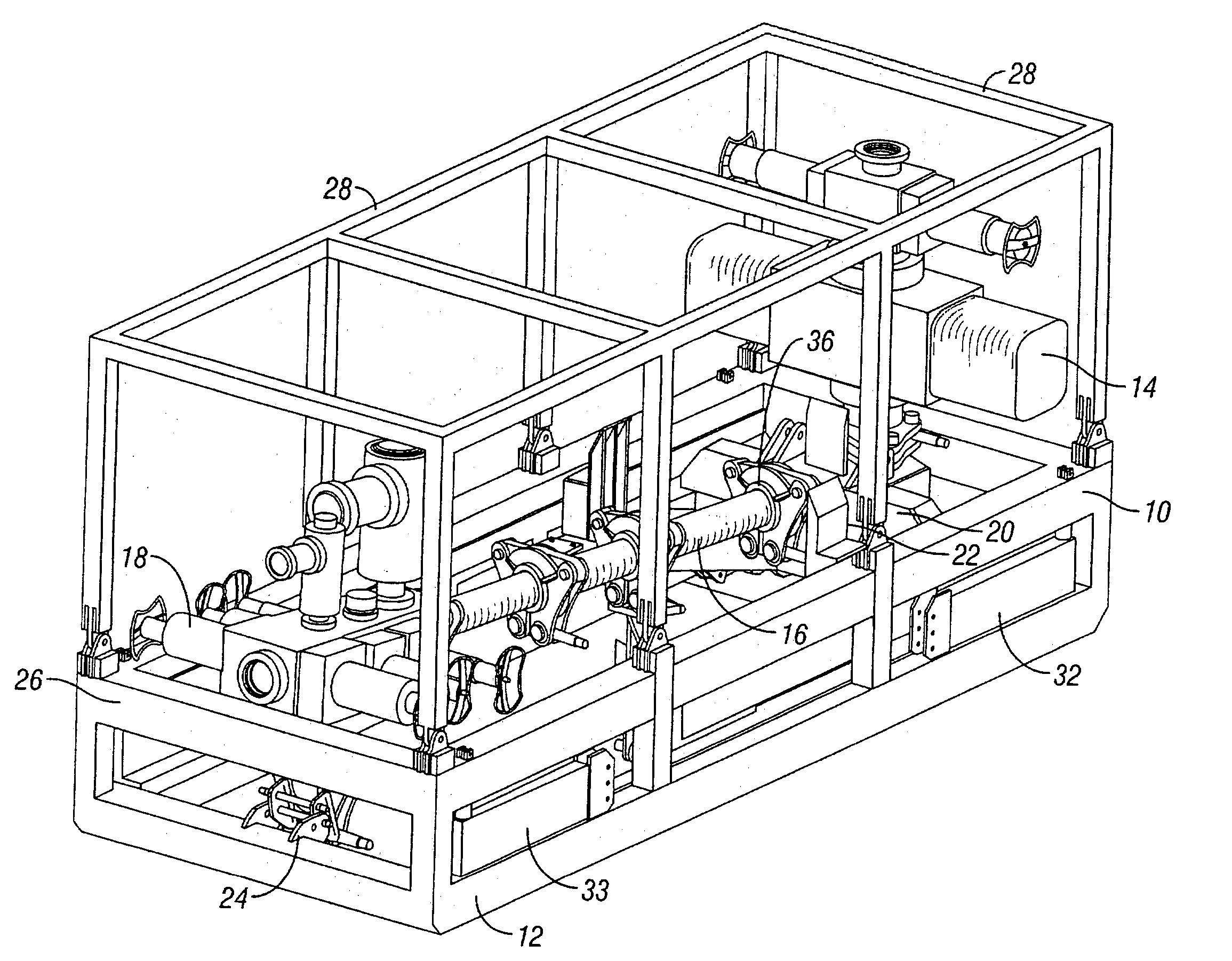
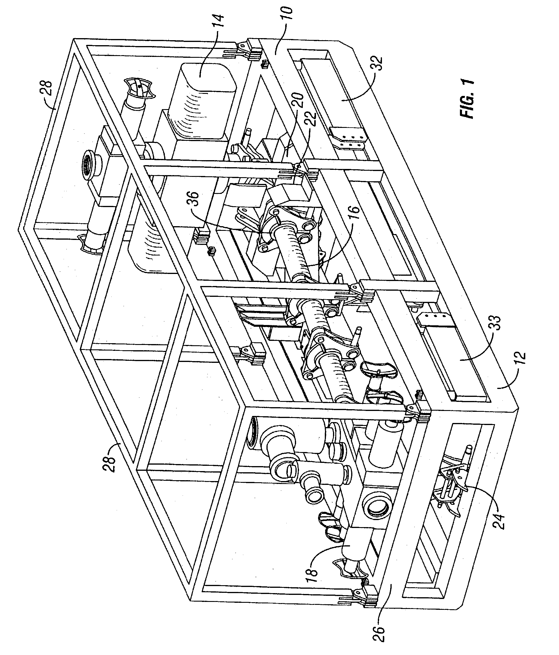
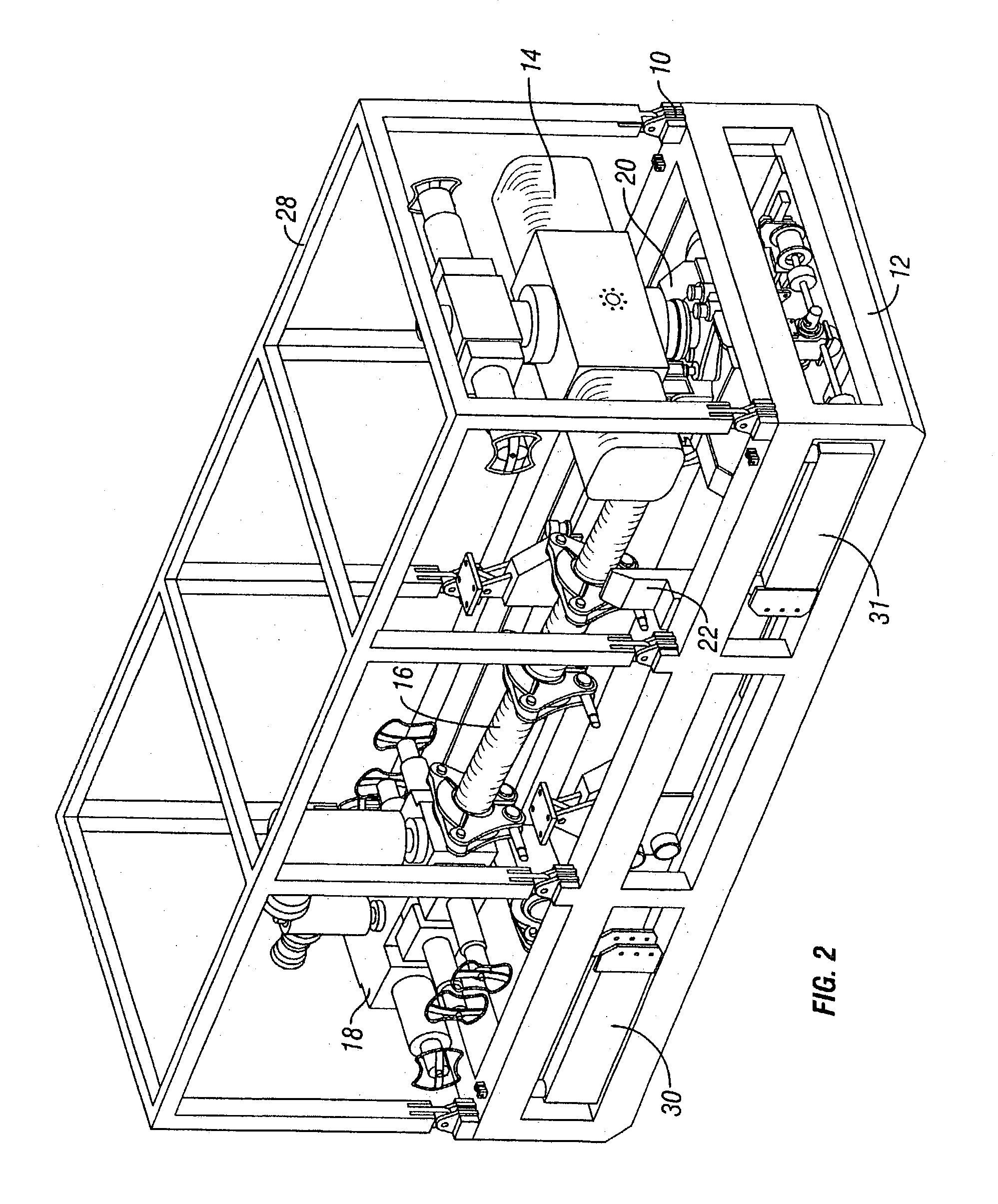
[0048]A typical BOP transport skid 10 is shown in FIGS. 1 and 2. The skid is a sturdy framework having a lower base 12 for supporting nesting safety head components 14, a riser 16 and a triple BOP stack 18. This configuration permits the components of the assembly to fit in an envelope suitable for standard transportation methods. Various support brackets 20, 22 and 24 secure the safety head, riser and BOP stack on the skid. This permits pre-assembly and testing of the safety head and pre-assembly of the riser / BOP at an off rig location. The upper rail 26 of the skid is adapted for supporting a transport crash frame 28 for protecting the various nested components while in transit and while stored. Four legs 30, 31, 32 and 33 are pivotally mounted on the skid, and as will be explained, provide leveling and stabilizing support for the skid when it is in its operating position. In a typical application, the lower end 36 of the riser 16 is pivotally mounted in bracket 22 so that it may ...


PUM


Abstract

A modular work system permits Rig Up time to be substantially reduced by reducing the number of crane lifts required to offload equipment for a transport boat or vehicle. This is achieved by developing transport skids capable of holding multiple system components. The number of equipment components that must be mechanically coupled on location is reduced by pre-assembling the components and maintaining the assembly in operating condition during storage and transport. Skid design concepts are employed, wherein a skid system carries various pre-assembled components for transport, storage and operation. Specifically, a skid sub-system includes various related components. The components are either pre-assembled or are designed to complete a sub-assembly through final assembly on the rig. The skid is moved into place using the crane, and the assembly is completed. Additional sub-systems are mounted on additional skids which are designed to be mated with the other related skids and sub-assemblies. Each skid sub-system fits in an envelope meeting transportation regulations for vehicle width and height. The system is particularly suitable for jacking frame operations.

Description

[0001]This patent application claims the benefit of provisional patent application U.S. Ser. No. 60 / 386,166, filed on Jun. 04, 2002, which is hereby incorporated by reference in its entirety.BACKGROUND OF THE INVENTION[0002]1. Field of the Invention[0003]The subject invention is generally related to modular systems for work functions on a drilling or production rig or platform and is specifically directed to the composition, operation, and performance of a skid based modular system for coiled tubing and similar operations.[0004]2. Discussion of the Prior Art[0005]Various operations are routinely performed on drilling and production platforms. Each of the operations includes subsets of equipment and specific operational functions associated with the equipment. By way of example, a coiled tubing operation includes a plurality of different processes or sequences of actions, some of which can be viewed as general to the service and some of which can be viewed as specific to the particul...

Claims


Application Information

Patent Timeline
Patent Type & Authority Patents(United States)
IPC IPC(8): E21B19/00E21B33/064E21B41/00E21B15/00E21B19/22
CPCE21B19/22E21B15/003
Inventor POLSKY, YAROMSHAMPINE, RODMCCAFFERTY, TERRY
Owner SCHLUMBERGER TECH CORP
Why Eureka
Try Eureka