Torsional vibration damper

a technology of vibration damper and torsional shaft, which is applied in the direction of fluid coupling, rotary clutch, gearing, etc., can solve problems such as noise, and achieve the effects of reducing the number of components, soft overall elasticity, and reducing the frequency of resonant sound

Active Publication Date: 2006-07-11
ZF FRIEDRICHSHAFEN AG
View PDF9 Cites 37 Cited by
  • Summary
  • Abstract
  • Description
  • Claims
  • Application Information

AI Technical Summary

Benefits of technology

[0016]It should be pointed out again that a “turbine damper” is identified by the ability of its takeoff-side transmission element to rotate relative to the turbine wheel, which helps to form part of the hydrodynamic circuit. A design is preferred here in which the takeoff-side transmission element of the torsional vibration damper is attached to the hub of the turbine wheel, whereas the turbine wheel itself has a base, which is formed on the turbine wheel shell and which allows the wheel to rotate relative to the turbine wheel hub.
[0027]The hydrodynamic clutch arrangement with the torsional vibration damper according to the invention can have only a single friction surface between the housing cover of the clutch housing and the piston of the bridging clutch, but, to increase the amount of torque which can be transmitted by the bridging clutch, the number of friction surfaces can be increased by providing at least one plate axially between the housing cover and the piston. If two or more plates are introduced into the bridging clutch, it is advantageous to interleave intermediate plates, which are connected nonrotatably to the housing cover, between the first plates. When the bridging clutch is designed with, for example, two plates and one intermediate plate, a total of four friction surfaces is obtained, which gives this bridging clutch the ability to transmit very high torques. It doesn't matter whether the plates are designed with friction linings on both sides and the intermediate plate carries no linings or whether the plates are designed without friction linings on the sides facing the intermediate plate and the intermediate plate carries friction linings on both sides.

Problems solved by technology

No influence, however, can be exerted on the fourth resonant frequency EF4, which means that noise can occur when the rpm range associated with it is reached.

Method used


Image

  • Torsional vibration damper
  • Torsional vibration damper
  • Torsional vibration damper

Examples


Embodiment Construction

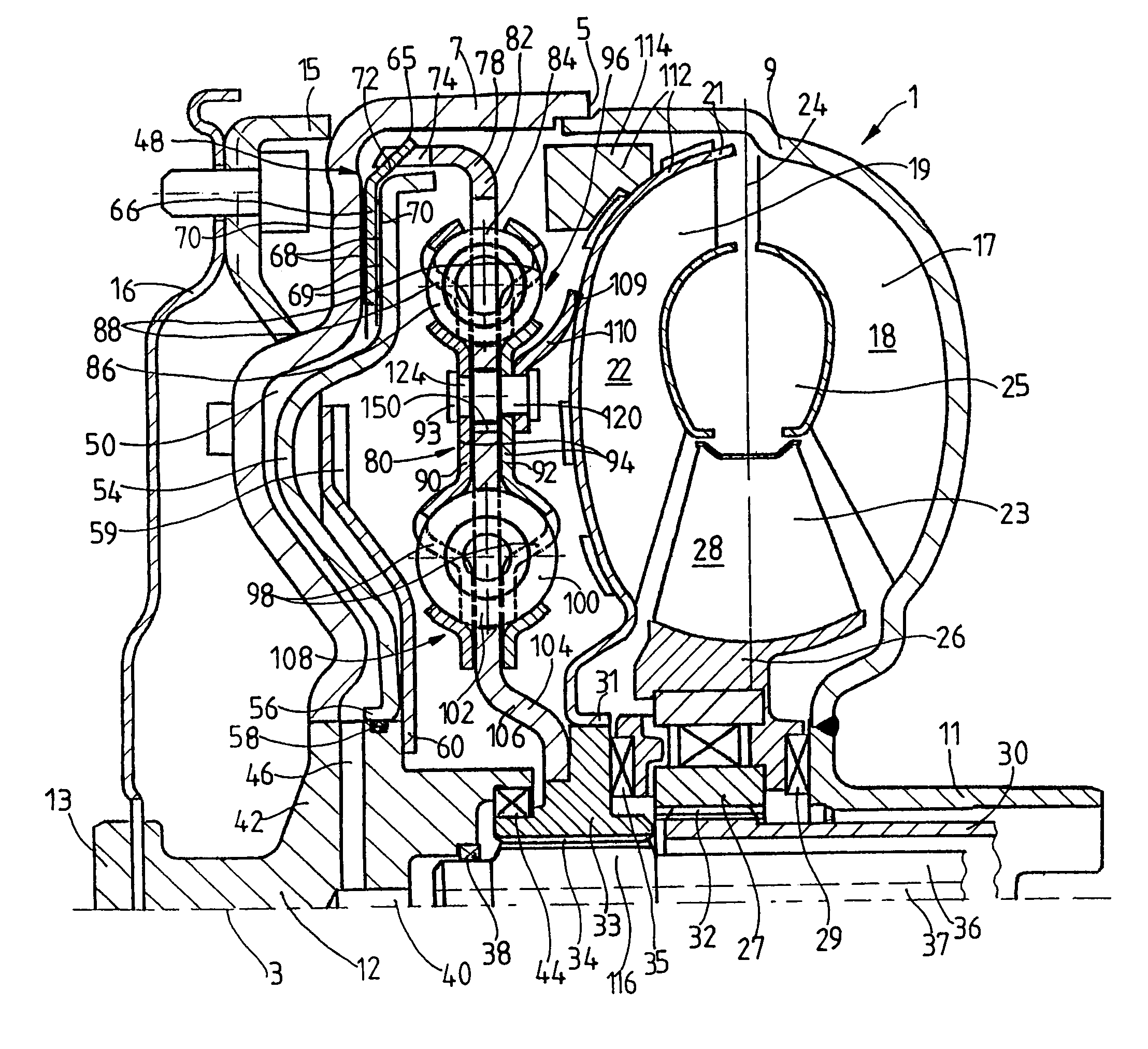
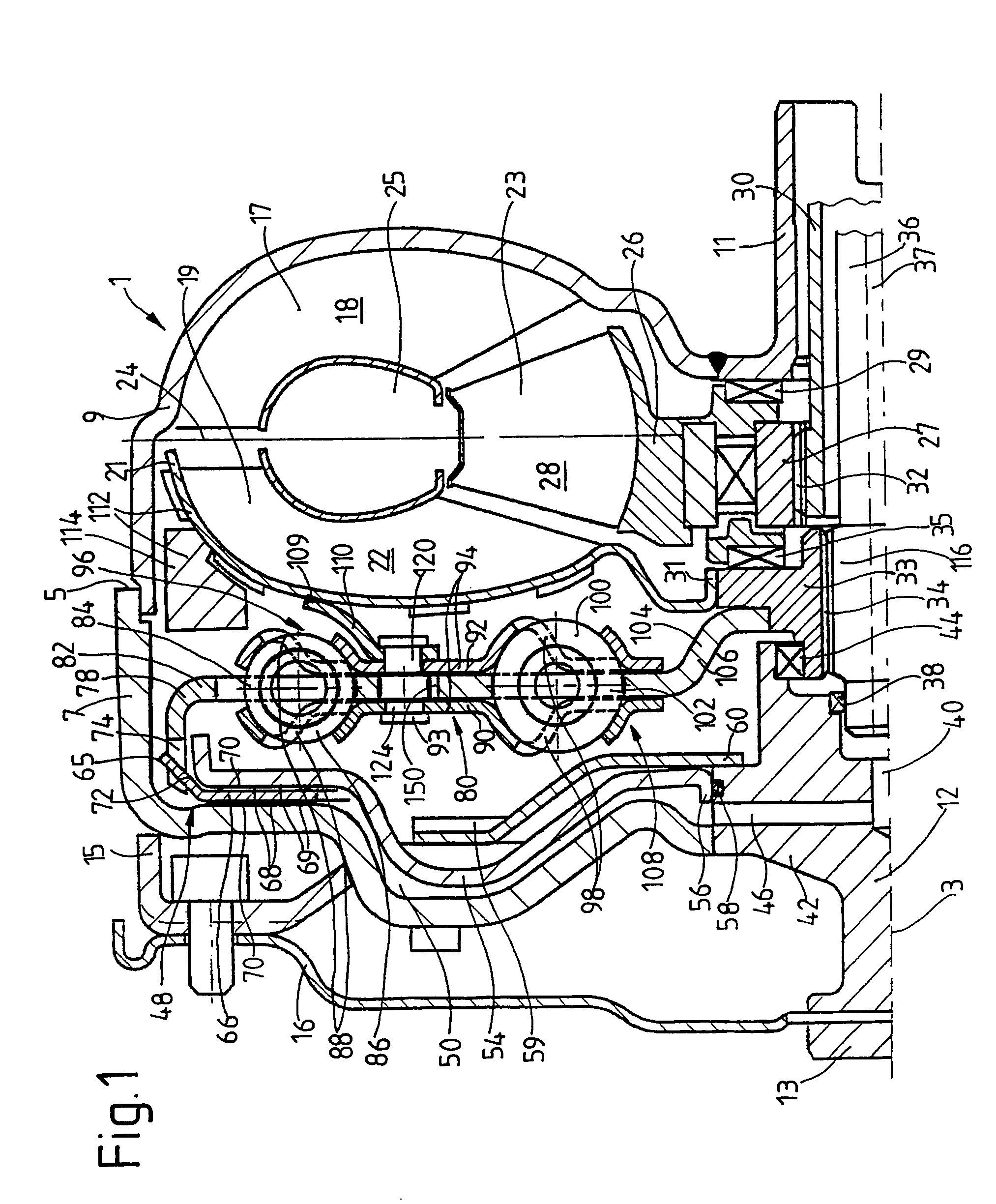
[0042]FIG. 1 shows a hydrodynamic clutch arrangement 1 in the form of a hydrodynamic torque converter, which is able to rotate around an axis of rotation 3. The hydrodynamic clutch arrangement 1 has a clutch housing 5, which has a housing cover 7 on the side facing a drive unit (not shown), such as an internal combustion engine. The housing cover is permanently connected to a pump wheel shell 9. The radially inner area of the shell merges into a pump wheel hub 11.

[0043]To return to the housing cover 7, this cover has, in its radially inner area, a journal hub 12 carrying a bearing journal 13. The bearing journal 13 is mounted in a manner known in itself and therefore not presented in detail on an element of the drive unit, such as a crankshaft, to center the clutch housing 5 on the drive side. The housing cover 7 also has a fastening bracket 15, which is used to attach the clutch housing 5 to the drive, preferably by way of a flexplate 16. FIG. 1 of U.S. Pat. No. 4,523,916, which is...


PUM


Abstract

A torsional vibration damper on the bridging clutch of a hydrodynamic clutch arrangement has a first connecting device, which can be brought into working connection with the clutch housing and with a drive-side transmission element. The drive-side transmission element is connected via first energy-storage devices to an intermediate transmission element. The torsional vibration damper also has a second connecting device for establishing a working connection via second energy-storage devices between the intermediate transmission element and a takeoff-side transmission element, which is connected to a takeoff-side component of the hydrodynamic clutch arrangement. The intermediate transmission element accepts a mass element, located operatively between the two connecting devices.

Description

BACKGROUND OF THE INVENTION[0001]1. Field of the Invention[0002]The invention pertains to a torsional vibration damper in the bridging clutch of a hydrodynamic clutch arrangement having an axis of rotation, a clutch housing, a turbine wheel, and a takeoff-side component, wherein the torsional vibration damper includes a drive-side connecting device comprising a drive-side transmission element which can be connected to the clutch housing; a takeoff-side connecting device comprising a take-off side transmission element which can be connected to the takeoff-side component; an intermediate transmission element between the connecting devices; first energy storage devices connecting the intermediate transmission element to the drive-side connecting device; and second energy storage devices connecting the intermediate transmission element to the takeoff-side connecting device.[0003]2. Description of the Related Art[0004]A torsional vibration damper of this type is known from, for example, ...

Claims


Application Information

Patent Timeline
Patent Type & Authority Patents(United States)
IPC IPC(8): F16D47/02F16F15/123F16F15/137F16H45/02
CPCF16F15/12366F16H45/02F16H2045/007F16H2045/0226F16H2045/0294F16H2045/0247F16H2045/0278F16H2045/0284F16H2045/0231
Inventor SASSE, CHRISTOPHSUDAU, JORGRONNEBECK, RALFACKERMANN, JURGENFREY, PETERWACK, ERWINZERNER, FRANK
Owner ZF FRIEDRICHSHAFEN AG
Why Eureka
Try Eureka