Suspension system, in particular for a working machine

a suspension system and working machine technology, applied in the direction of shock absorbers, pedestrian/occupant safety arrangements, tractors, etc., can solve the problems of disruptive vehicle spring deflection under load, inability to control the movement of the vehicle or the operating machine, and in principle inacceptable situation, so as to eliminate the disadvantages

Inactive Publication Date: 2006-07-11
HYDAC TECH GMBH
View PDF10 Cites 7 Cited by
  • Summary
  • Abstract
  • Description
  • Claims
  • Application Information

AI Technical Summary

Benefits of technology

[0006]Objects of the present invention are to provide an improved spring suspension system which eliminates the disadvantages described in conventional systems. The desired objects are basically achieved by a spring suspension system having an equalization device with an additional switching valve for control of the rod side of a suspension cylinder within the supply device. In a branch line, a load monitoring system is connected to a line with components of the locking device as well as to the associated suspension cylinder for the piston side of the suspension cylinder. The load monitoring system controls the pressure supply for the content of the required system pressure. By the equalization device, pressure equalization of the system can be affected on the currently prevailing load pressure before the spring suspension is reactivated. Hence, with the spring suspension system of the present invention, pressure equalization between the suspension cylinder and the associated suspension reservoir is effected. Thus, uncontrolled movement of the shaft is prevented when the suspension system is engaged, independently of the change in load.

Problems solved by technology

Since the load situation is unknown after such operations as the vehicle continues in movement or starts movement, in the conventional spring suspension systems movement of the vehicle or operating machine is not controlled when the suspension is unlocked.
This lack of control is in principle an unacceptable situation.
Although the disclosed solution achieves an especially soft suspension in addition to the level adjustment, disruptive vehicle spring deflections occur under load, as indicated above.
Even with this suspension system the disadvantages of the state of the art cannot be avoided.

Method used


Image

  • Suspension system, in particular for a working machine
  • Suspension system, in particular for a working machine
  • Suspension system, in particular for a working machine

Examples


Embodiment Construction

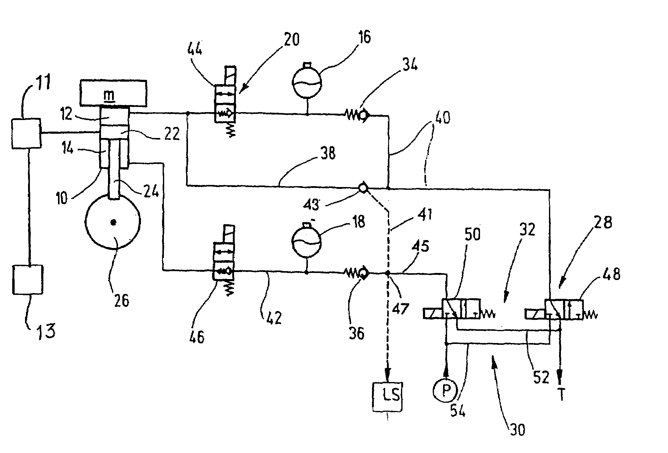
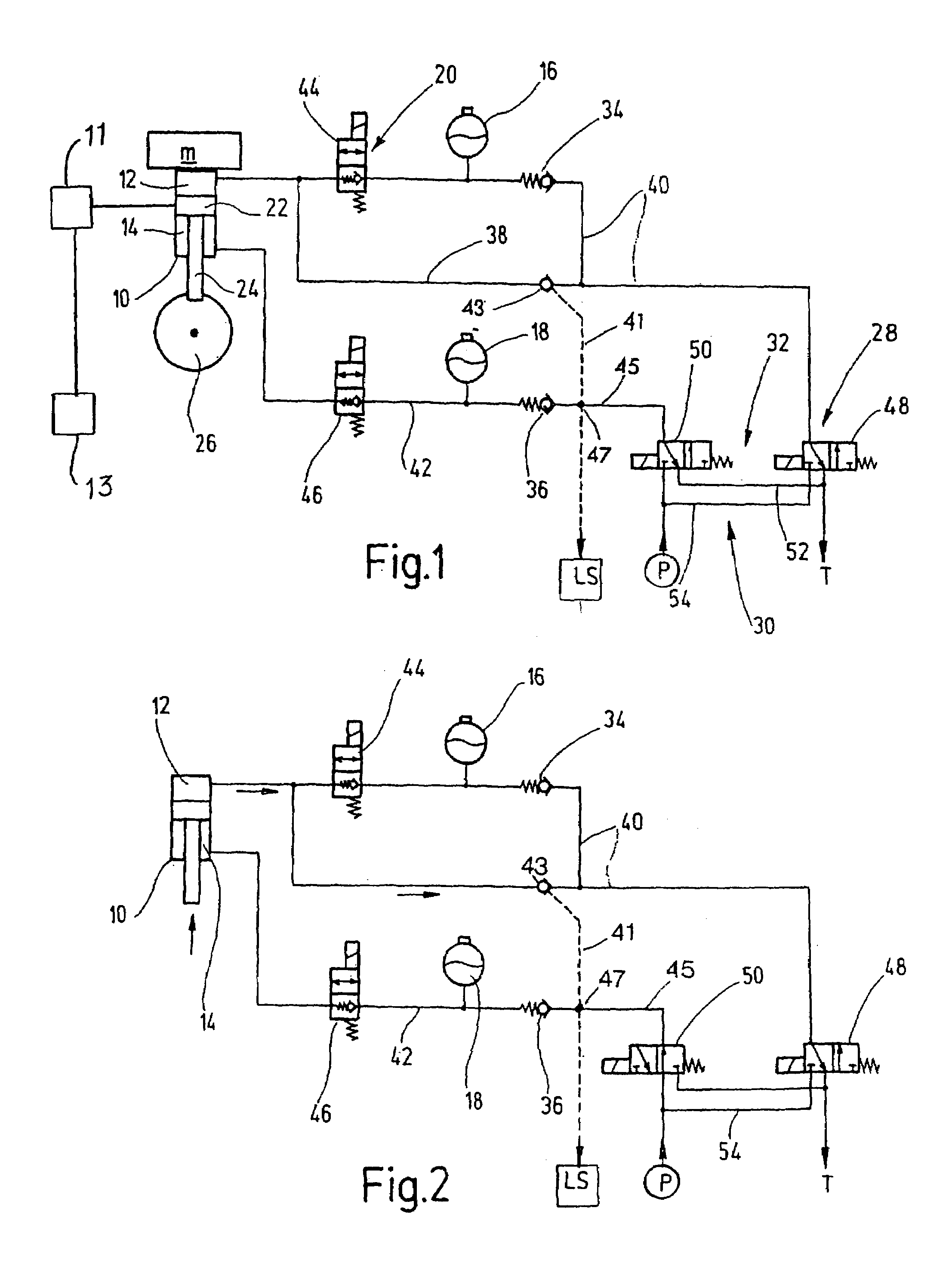
[0014]The spring suspension in FIG. 1 is shown in its locked state, that is, the suspension feature of the suspension system is disabled.

[0015]This spring suspension system has a suspension cylinder 10 to which varying load pressures m may be applied. The piston side 12 and piston rod side 14 may each be connected to a respective suspension reservoir 16 or 18 by a locking device 20. The locking device 20 locks the spring suspension in the switched state illustrated. The suspension cylinder 10 is connected by its housing to a vehicle body (not shown in detail), and is linked at the free end of the piston rod 24, connected to the piston 22, to a vehicle wheel 26. A plurality of vehicle wheels together with associated suspension cylinders (not shown) ensures operability of the machine, such as a tractor or the like. The spring suspension system also has an equalization device 28 which engages or disengages the cylinder with the aid of a supply device 30.

[0016]As FIG. 1 also shows, the ...


PUM


Abstract

A suspension system, in particular for a working machine, such as a tractor or similar device, with a suspension cylinder (10) is subjected to various load pressures (m). The piston slide (12) and rod side (14) of the system may each be connected to a suspension reservoir (16, 18). A locking device (20) locks the suspension and, with an equalization device (28) having a switching valve (48) within the supply device, controls the piston side (12) of the suspension cylinder (10). A pressure supply (P) supplies the system pressure necessary for the suspension system. A pressure equalization of the system to the relevant load pressure can be performed before renewed operation by the equalization device. The equalization device (28) includes a further switching valve (50) within the supply device (30) for control of the rod side (14) of the suspension cylinder (10). A load monitoring device (LS) is connected to parts of the stop device (20). The associated suspension reservoir (16) for the piston side (12) of the suspension cylinder (10) is in a branch (38) of a line (40).

Description

FIELD OF THE INVENTION[0001]The present invention relates to a suspension system, in particular for a working machine such as a tractor or the like, with a suspension cylinder to which varying load pressures may be applied. A suspension cylinder whose piston and rod side may each be connected as required to a suspension reservoir by a locking device which locks the spring suspension system. An equalization device, having a switching valve, controls the piston side of the suspension cylinder inside the supply device. A pressure supply provides the system pressure needed in the suspension system.BACKGROUND OF THE INVENTION[0002]In certain spring suspension systems, for example for machines such as tractors or the like, it may be advisable to stop such machines, for example, at a speed below an assignable speed of the machine. This stopping is accomplished by locking the hydropneumatic suspension when the vehicle is moving at low speeds or is stationary. Operations, such as hoisting an...

Claims


Application Information

Patent Timeline
Patent Type & Authority Patents(United States)
IPC IPC(8): B60G17/04B60G17/005
CPCB60G17/005B60G2202/154B60G2500/20B60G2300/082B60G2204/8304
Inventor HUTH, HEINZ-PETER
Owner HYDAC TECH GMBH
Why Eureka
Try Eureka