Head rests

a head rest and vehicle seat technology, applied in the direction of chairs, movable seats, pedestrian/occupant safety arrangements, etc., can solve the problems of insufficient prevention of whiplash injury of passengers, inability to suitably hold the head rests of passengers, etc., and achieve good performance

Inactive Publication Date: 2006-07-11
TOYOTA BOSHOKU KK
View PDF12 Cites 45 Cited by
  • Summary
  • Abstract
  • Description
  • Claims
  • Application Information

AI Technical Summary

Benefits of technology

[0008]It is, accordingly, one object of the present invention to provide improved head rests of a vehicle, in particular, to provide head rests of a vehicle that can achieve good performance when the vehicle is applied with an impact.
[0010]According to the head rest thus constructed, when a vehicle collision is sensed or predicted, the front portion of the head rest main body can timely or immediately move to a desired height in order to align with a head of a passenger. Therefore, the passenger head can be reliably held by the head rest. As a result, the passenger can be effectively prevented from suffering a whiplash injury.
[0012]In this case, the head rest can be designed such that the moving mechanism can be stopped in response to a proximity signal from the proximity detecting device. Therefore, it is possible to prevent the front portion of the head rest main body from excessively projecting toward the passenger head.

Problems solved by technology

Consequently, the passenger head cannot be suitably held by the head rest.
This means that the passenger cannot be sufficiently prevented from suffering a whiplash injury.

Method used


Image

  • Head rests
  • Head rests
  • Head rests

Examples


first embodiment

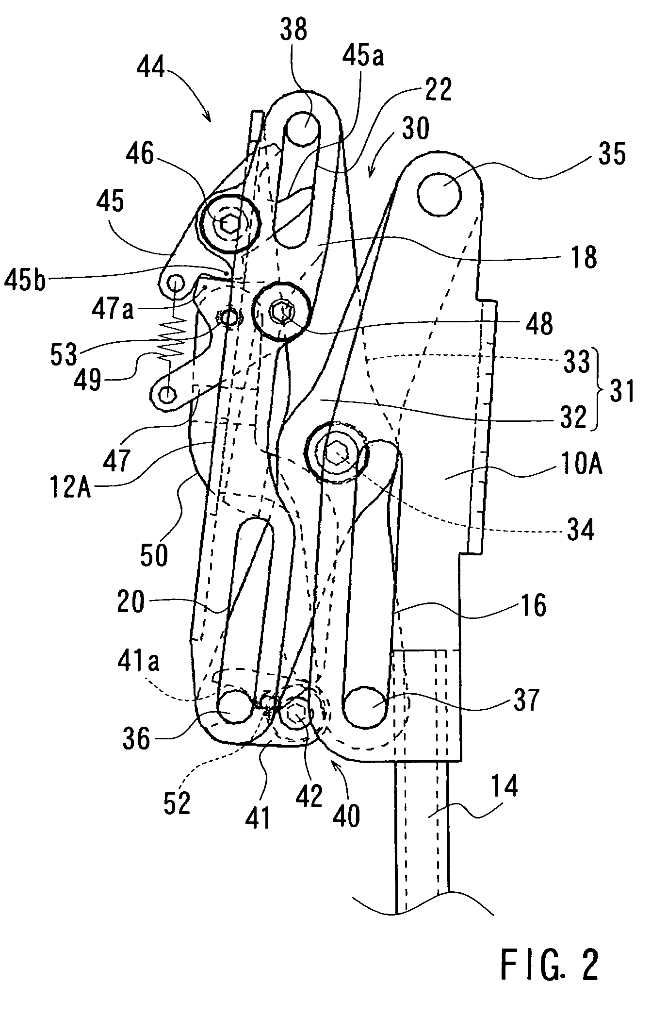
[0064]Similar to the first embodiment, the moving mechanism 30 essentially consists of a pair of cross bar links 31. Each of the cross bar links 31 is composed of the outer and inner cross bars 32 and 33 that are rotatably interconnected via the pivot pin 34. In this embodiment, the outer cross bars 32 of the respective pairs of cross bar links 31 are rotatably interconnected at their front and rear end portions (i.e., first and second end portions) via the first connector shaft 35 and the second connector shaft 36. Similarly, the inner cross bars 33 of the respective pairs of cross bar links 31 are rotatably interconnected at their front and rear end portions (i.e., first and second end portions) via the first connector shaft 37 and the second connector shaft 38.

[0065]Unlike the first embodiment, the first connector shaft 35 has opposed ends that are respectively movably connected to lower ends of the retainer member 18. Also, the first connector shaft 37 has opposed ends that resp...

third embodiment

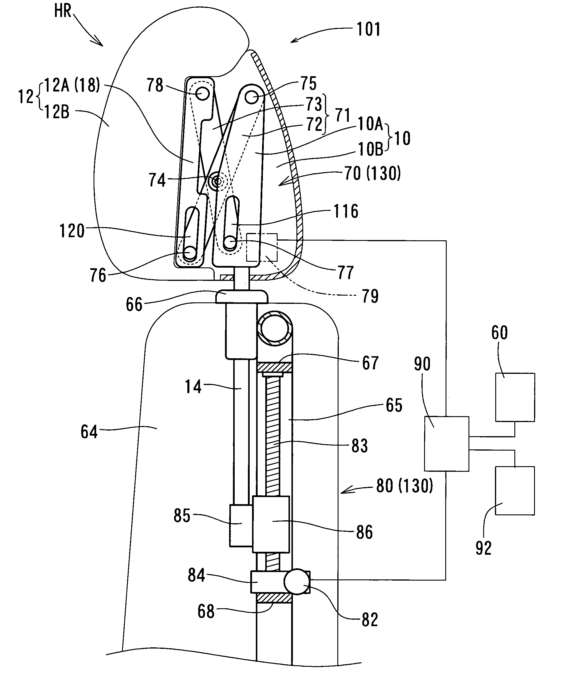
[0090]The seat back 64 in the third embodiment can be modified, if necessary. For example, as shown in FIG. 13(A), a modified seat back 64′ of this embodiment can be formed with a receiving space or recessed portion 64a so that the main body HR of the head rest 101 can be received or retracted therein when the second moving mechanism 80 is in the lowered condition, as shown by a solid line. Further, at this time, the rear portion 10 and the front portion 12 of the main body HR are closed or joined with each other. According to this modified form, because the main body HR can normally be retracted into the seat back 64′, the passenger can be freed from a possibly oppressive feeling attributed to the presence of the head rest.

[0091]In this modified form, when the vehicle collision is sensed or predicted by the sensor 92, the second moving mechanism 80 is operated so as to shift from the lowered condition to the lifted condition. As a result, as shown by a broken line, the main body HR...


PUM


Abstract

A head rest of a vehicle seat may include a main body having a front portion for supporting a head of a passenger and a rear portion that is attached to a head rest stay, a moving mechanism that is arranged and constructed to move the main body or the front portion vertically and to move the front portion back and forth, and a control device that is arranged and constructed to control motions of the moving mechanism. The moving mechanism includes a first moving mechanism for upwardly moving the main body or the front portion and a second moving mechanism for forwardly moving the front portion. The control device controls the motions of the moving mechanism based upon a detection signal that is generated when a vehicle collision is predicted or sensed, so that the second moving mechanism is actuated after the first moving mechanism is actuated.

Description

BACKGROUND OF THE INVENTION[0001]1. Field of the Invention[0002]The present invention relates to head rests of a vehicle seat. More particularly, the present invention relates to head rests of a vehicle seat that can increase restraint performance for heads of passengers when a vehicle collision is sensed or predicted.[0003]2. Description of the Related Art[0004]A head rest of a vehicle seat that can increase restraint performance for a head of a passenger when a vehicle collision is sensed or predicted is already known. Such a head rest (an active head rest) is taught, for example, by Japanese Laid-Open Patent Publication Number 2002-142910.[0005]The known head rest includes two portions, i.e., a forward movable portion and a rearward immovable portion, that are linked to each other via parallel linking members. In the known head rest, when the vehicle collision is sensed by a sensor, the parallel linking members are actuated based on a signal from the sensor so that the movable po...

Claims


Application Information

Patent Timeline
Patent Type & Authority Patents(United States)
IPC IPC(8): B60N2/42A47C1/10B60N2/02B60N2/48
CPCB60N2/0232B60N2/4829B60R21/01532B60N2/4885B60N2/4832B60R2021/0048B60N2/888B60N2/829B60N2/832B60N2/02246
Inventor AKAIKE, FUMITOSHINISHIMURA, SEIYA
Owner TOYOTA BOSHOKU KK
Why Eureka
Try Eureka