DC-DC converter

a converter and dc technology, applied in the direction of dc-dc conversion, power conversion systems, instruments, etc., can solve the problems of increasing switching loss, complicated control circuit, design difficulties, etc., and achieve the effect of simplifying the configuration of the control section

Inactive Publication Date: 2006-07-11
PANASONIC CORP
View PDF7 Cites 19 Cited by
  • Summary
  • Abstract
  • Description
  • Claims
  • Application Information

AI Technical Summary

Benefits of technology

[0051]The DC—DC converter of the present invention configured as described above enables control from voltage step-up to voltage step-up and step-down and f

Problems solved by technology

The DC—DC converter of the above-mentioned U.S. Pat. No. 4,395,675 requires a plurality of error voltages Ve1 and Ve2, thereby to cause the problem of complicating the control circuit.
Further, during voltage step-up and step-down operation in which both the first switch 32 and the second swit

Method used


Image

  • DC-DC converter
  • DC-DC converter
  • DC-DC converter

Examples


first embodiment

[0066]A first embodiment of the present invention will be described referring to FIG. 1 to FIG. 3.

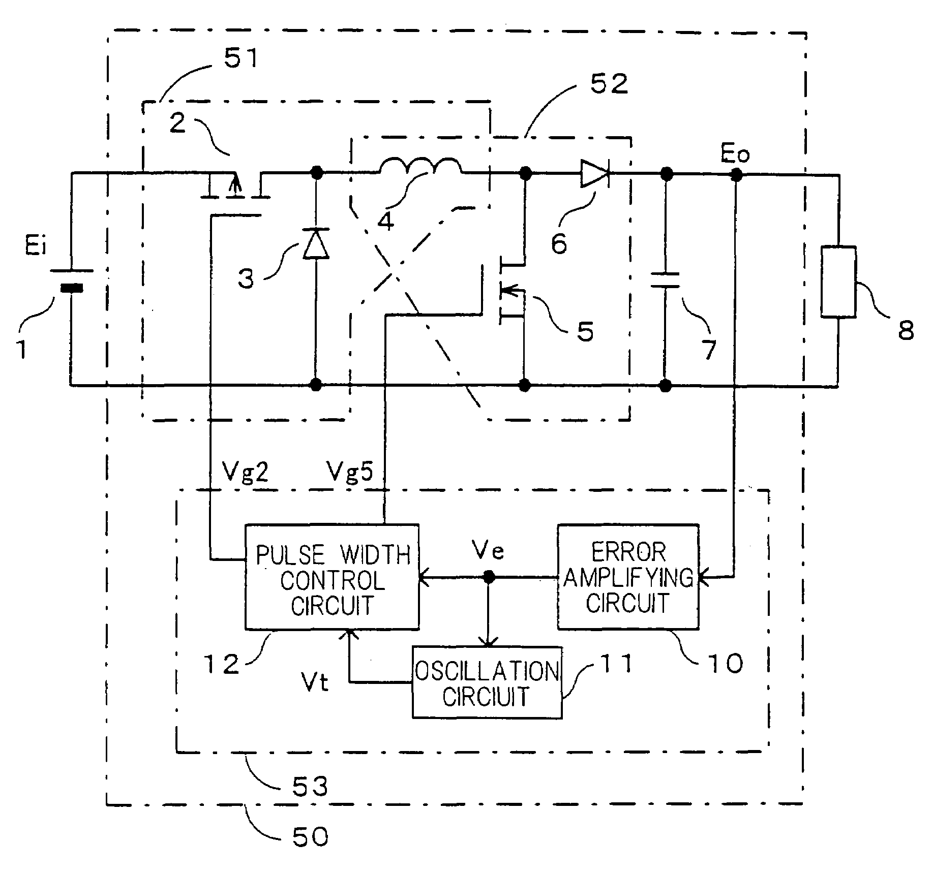
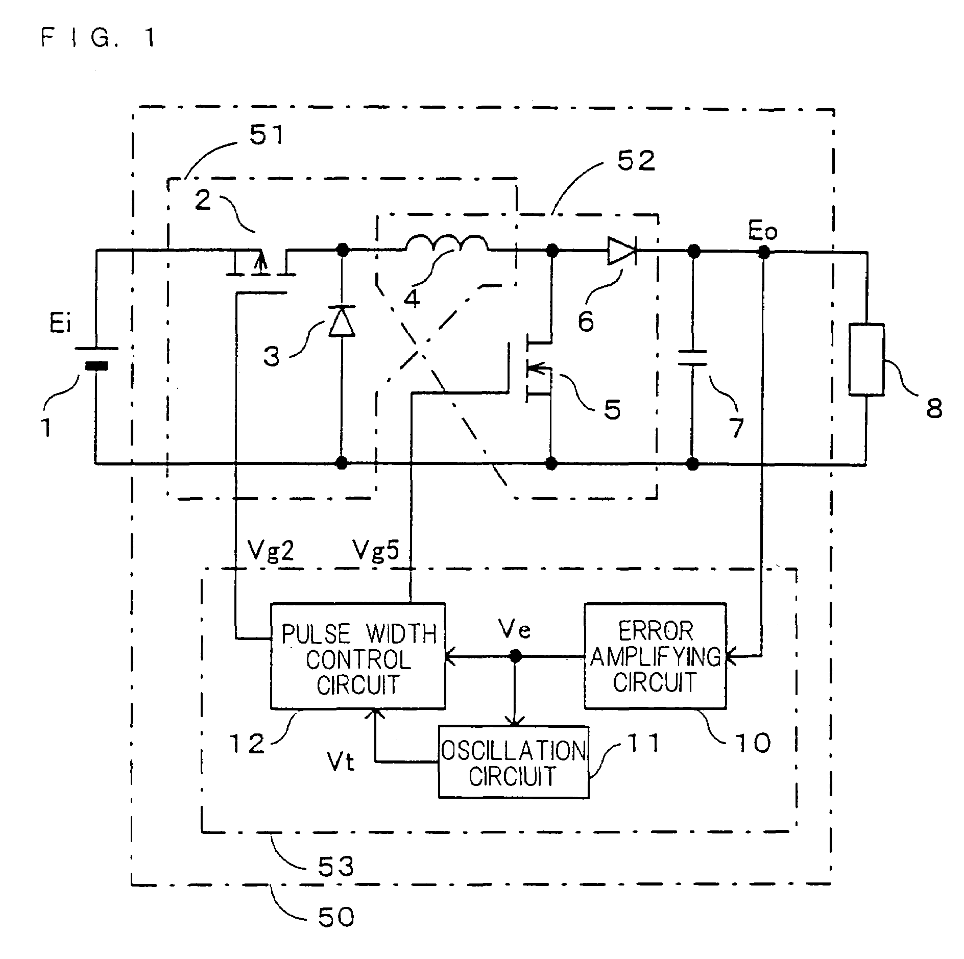
[0067]FIG. 1 is a circuit diagram showing configuration of a DC—DC converter in accordance with the first embodiment of the present invention. In FIG. 1, the DC—DC converter 50 of the first embodiment comprises a voltage step-down converter 51 consisting of a first switch 2 formed of a P-channel MOSFET, which is connected to a direct current input power source 1 of a voltage Ei, a first rectifying section 3 as a diode and an inductor 4; a voltage step-up converter 52 consisting of a second switch 5 formed of N-channel MOSFET and a second rectifying section 6 as a diode, having the inductor 4 in common; and an output capacitor 7. A voltage Eo between both terminals of the output capacitor 7 is applied to a load 8 as a direct current output voltage.

[0068]The first switch 2, the inductor 4 and the second switch 5 are connected in series across a positive pole 1A and a negative pole 1B of t...

second embodiment

[0119]A DC—DC converter in accordance with a second embodiment of the present invention will be described referring to FIG. 4 and FIG. 5.

[0120]FIG. 4 is a circuit diagram showing the configuration of a control section 53A of the DC—DC converter in accordance with the second embodiment of the present invention. The control section 53A is incorporated into the converter section 50 in place of the control section 53 shown in FIG. 1 to constitute the DC—DC converter in accordance with the second embodiment. In the control section 53A of the DC—DC converter in accordance with the second embodiment, the error amplifying circuit 10 and the pulse width control circuit 12 are the same as those of the control section 53 of the DC—DC converter in accordance with the first embodiment. Further, as will be described in detail below, an oscillation circuit 11A is the same as the above-mentioned oscillation circuit 11 of the control section 53 except for a part. In FIG. 4, the same reference numera...

third embodiment

[0143]FIG. 6 is a block diagram and a circuit diagram of a control section 53B of a DC—DC converter in accordance with a third embodiment of the present invention. The DC—DC converter in accordance with the third embodiment is configured by replacing the control section 53 of the converter section 50 shown in FIG. 1 with the above-mentioned control section 53B. In FIG. 6, the error amplifying circuit 10 and the pulse width control circuit 12 are the same as those in FIG. 2 or FIG. 4, and therefore they are illustrated in block diagram. The same reference numerals are applied to elements in an oscillation circuit 11B having the same function and configuration as those of the oscillation circuit 11A shown in FIG. 4 and description thereof are omitted. The control section 53B of the DC—DC converter in accordance with the third embodiment is different from the control section 53A of the DC—DC converter in accordance with the second embodiment shown in FIG. 4 in that, in the oscillation ...


PUM


Abstract

A DC—DC converter that receives input of a direct current voltage such as a battery and supplies a controlled direct current voltage to a load is simplified. It comprises a voltage step-down converter section consisting of a first switch 2, a first rectifying means 3 and an inductor 4, a voltage step-up converter section consisting of an inductor 4, a second switch 5 and a second rectifying means 6, and a control section consisting of an output capacitor 7, an error amplifying circuit 10, an oscillation circuit 11 and a pulse width control circuit 12. An oscillation voltage Vt from the oscillation circuit 11 is compared with an error voltage Ve from the error amplifying circuit 10 and a duty ratio of each switch is adjusted to control the operation of voltage step-down, voltage step-up and step-down, and voltage step-up.

Description

CROSS-REFERENCE TO RELATED APPLICATION[0001]This application is a Section 371 of International Application No. PCT / JP02 / 13044, filed Dec. 12, 2002, the disclosure of which is incorporated herein by reference.TECHNICAL FIELD[0002]The present invention relates to a DC—DC converter which is used for various electronic apparatuses, receives a direct current voltage input from a battery or the like and supplies a controlled direct current voltage to a load, and more particularly relates to a DC—DC converter capable of carrying out voltage step-up and step-down in an input and output noninverting state.BACKGROUND ART[0003]FIG. 10(a) and FIG. 10(b) show a prior art of a DC—DC converter for stepping up or stepping down a direct current voltage input from a direct current power source such as a battery in an input and output noninverting state (the state wherein the polarity of the direct current input voltage is the same as that of the direct current output voltage) and supplying the direct...

Claims


Application Information

Patent Timeline
IPC IPC(8): G05F1/24G05F1/62H02M3/158
CPCH02M3/1582
Inventor ISHII, TAKUYASAITO, HIROSHI
Owner PANASONIC CORP
Why Eureka
Try Eureka