Active-RC filter with compensation to reduce Q enhancement

a filter and compensation technology, applied in the field of activerc filter with compensation to reduce q enhancement, can solve the problems of low output impedance, low passband ripple across process, low frequency performance of these filters,

Inactive Publication Date: 2006-07-11
QUALCOMM INC
View PDF5 Cites 38 Cited by
  • Summary
  • Abstract
  • Description
  • Claims
  • Application Information

AI Technical Summary

Problems solved by technology

Unfortunately, the performance of these filters may suffer at high frequencies.
In particular, the limited gain-bandwidth product of each amplifying element may cause Q-enhancement.
One technique is to use “pre-distortion.” The problem with using pre-distortion is that it is difficult to achieve low passband ripple across process, voltage and temperature variations.
Another way to reduce Q-enhancement is to construct an amplifier with a final output buffer stage using a source follower resulting in low output impedance.
Unfortunately, the use of such a buffer stage may degrade performance, for example by limiting the output voltage swing of the operational amplifier and increasing the DC current of the operational amplifier.

Method used


Image

  • Active-RC filter with compensation to reduce Q enhancement
  • Active-RC filter with compensation to reduce Q enhancement
  • Active-RC filter with compensation to reduce Q enhancement

Examples


Embodiment Construction

[0035]The detailed description set forth below in connection with the appended drawings is intended as a description of various embodiments of the present invention and is not intended to represent the only embodiments in which the present invention may be practiced. The detailed description includes specific details for the purpose of providing a thorough understanding of the present invention. However, it will be apparent to those skilled in the art that the present invention may be practiced without these specific details. In some instances, well-known structures and devices are shown in block diagram form in order to avoid obscuring the concepts of the present invention. Acronyms and other descriptive terminology may be used merely for convenience and clarity and are not intended to limit the scope of the invention.

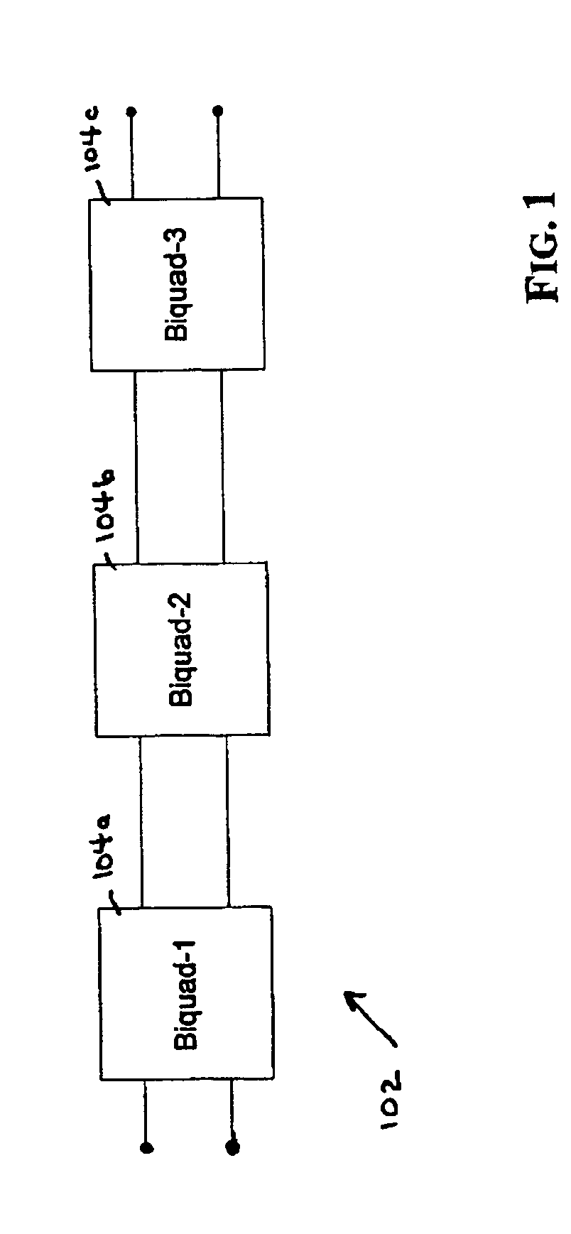
[0036]FIG. 1 is a functional block diagram of an active filter 102 with multiple biquad stages 104a–104c arranged in a cascaded fashion. Each biquad 104a–104c may be ...


PUM


Abstract

An active filter with compensation to reduce Q-enhancement is disclosed. The filter may include a first amplifier and a second amplifier coupled to the first amplifier. The second amplifier having a negative feedback loop including a buffer having a plurality of compensation resistors. The compensation resistors may each have a value that results in the biquad filter having substantially zero Q-enhancement. The biquads may cascaded to form higher order filters.

Description

BACKGROUND[0001]1. Field[0002]The present disclosure relates generally to electronics, and more specifically, to an active-RC filter with compensation to reduce Q-enhancement.[0003]2. Background[0004]Filters are used extensively today in almost every electronic application. A filter is an electrical network that alters the amplitude and / or phase characteristics of a signal as the frequency of the signal changes. Thus, a filter may be used in an electronic circuit to pass signals in certain frequency ranges and attenuate signals in other frequency ranges. The behavior of a filter may be described mathematically in the frequency-domain in terms of its transfer function. The transfer function describes, among other things, the ratio between the input signal amplitude and the output signal amplitude applied to the filter. The amplitude response curve describes the effect of the filter on the amplitude of the input signal at various frequencies. The steepness of the amplitude response cu...

Claims


Application Information

Patent Timeline
Patent Type & Authority Patents(United States)
IPC IPC(8): H03K5/00
CPCH03H11/1252H03H11/1234
Inventor GUDEM, PRASADGAZZERRO, PETER C.
Owner QUALCOMM INC
Why Eureka
Try Eureka