
Method and apparatus for high speed data compression and decompression

a data compression and high-speed technology, applied in the field of data compression and decompression, can solve the problems of generating block noise at the boundary of subbands, affecting encoding apparatus may impair the advantage of using wavelet conversion,

Inactive Publication Date: 2006-07-11
RICOH KK
View PDF10 Cites 9 Cited by
  • Summary
  • Abstract
  • Description
  • Claims
  • Application Information

AI Technical Summary

Benefits of technology

[0012]In addition, a data compression apparatus typically performs parallel processing in which a one-dimension input signal is divided into a plurality of blocks and these signals are input to analytic subband filter banks for performing parallel subband-analysis. In this case, the parallel processing is aimed to efficiently increase the speed of a data compression operation.

Problems solved by technology

However, such parallel operations with a discrete cosine transform (DCT)result in generating block noise at boundaries of subbands.
Accordingly, the data encoding apparatus may impair the advantage of using the wavelet conversion relative to DCT.
However, in particular when the analytic subband filter banks use three or more taps, storing each of the divided signals in an independently accessible memory causes a problem.
The problem is that extra memory access operations as well as extra memory access controls are required during the processing of the first and last blocks and also boundaries between blocks, which details will be explained later.
This problem interferes with the desired increase of processing speed and requires a complex configuration to avoid it.

Method used


Image

  • Method and apparatus for high speed data compression and decompression
  • Method and apparatus for high speed data compression and decompression
  • Method and apparatus for high speed data compression and decompression

Examples


Embodiment Construction

[0054]In describing preferred embodiments of the present invention illustrated in the drawings, specific terminology is employed for the sake of clarity. However, the present invention is not intended to be limited to the specific terminology so selected and it is to be understood that each specific element includes all technical equivalents which operate in a similar manner.

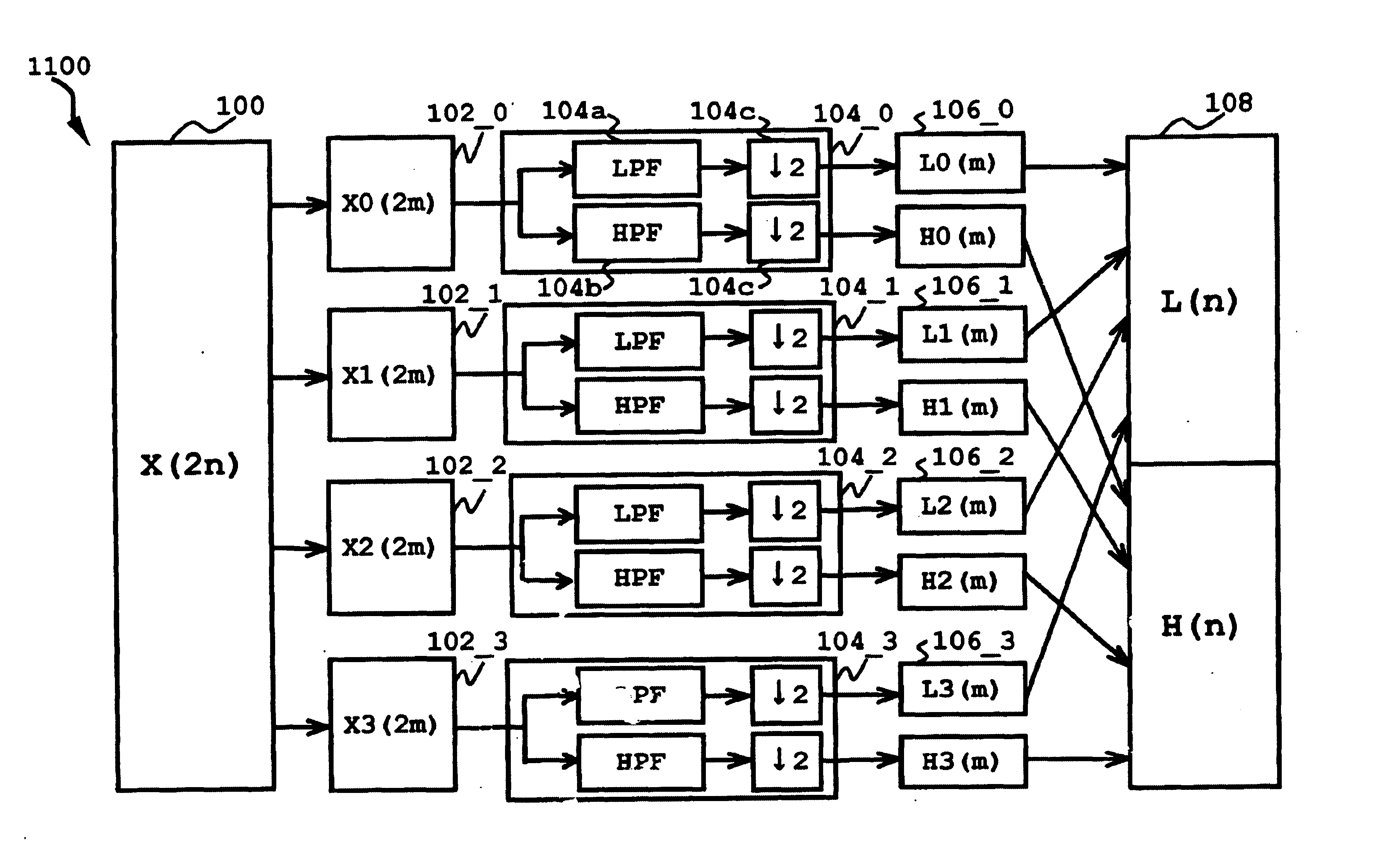
[0055]Referring now to the drawings, wherein like reference numerals designate identical or corresponding parts throughout the several views, and more particularly to FIG. 1 thereof, there is illustrated a block diagram of a subband forming apparatus 1100 according to an exemplary embodiment of the present invention. The subband forming apparatus 1100 of FIG. 1 performs a two-subband forming operation by first dividing a single-dimension signal x(2n) into four regional signals and then processing the four regional signals in parallel. The subband forming apparatus 1100 includes a signal source 100, memories 102_...


PUM


Abstract

A subband processing apparatus useful for wavelet conversion and compression-decompression operation includes a plurality of memories and a plurality of analytic filter banks. The plurality of memories store an input signal in a way such that the input signal is divided into a plurality of regional signals to correspond to the plurality of memories. The plurality of analytic filter banks analyzes in parallel the regional signals. Each analytic filter bank is configured to be in a one-to-one relationship with one of the plurality of memories. In this apparatus, each of the plurality of memories stores a corresponding regional signal other signal copied from the leading and trailing portions of other stored regional signals. Reverse processing is provided to synthesize a signal from a plurality of analyzed subband signals.

Description

CROSS-REFERENCE TO RELATED APPLICATIONS[0001]This application claims priority under 35 U.S.C. § 119 to Japanese patent application Nos. JPAP11-107722 filed on Apr. 15, 1999 and JPAP11-125623 filed on May 6, 1999, the entire contents of which are hereby incorporated by reference.BACKGROUND OF THE INVENTION[0002]1. Field of the Invention[0003]The present invention generally relates to a method and apparatus for data compression and decompression, and more particularly to a method an d apparatus for compression and decompression which improves operation speed by employing parallel signal processing in an efficient manner.[0004]2. Discussion of the Background[0005]A variety of data compression apparatuses have been developed for use in the computer area. As an example, FIG. 24 shows a typical wavelet conversion apparatus which includes a wavelet converter 800 and an encoder 801. The wavelet converter 800 is configured to perform a two-layered wavelet conversion, and includes analytic su...

Claims


Application Information

Patent Timeline
Patent Type & Authority Patents(United States)
IPC IPC(8): G06K9/46G06K9/00G06K9/36G06K9/40G06K9/54G06T9/00H04N7/26
CPCG06T9/007H04N19/63H04N19/436H04N19/423H04N19/42
Inventor TERAO, NORIYUKI
Owner RICOH KK
Learn More