Block boundary artifact reduction for block-based image compression

a block-based image and artifact reduction technology, applied in the field of digital image reproduction, can solve the problems of inability to achieve digital transmission and storage of images, noticeable change in pixel intensity across the boundary between blocks of the reconstructed image, and inability to achieve and improve block boundary artifact reduction. , the effect of reducing the abrupt transition between blocks

Inactive Publication Date: 2006-07-11
RAKUTEN GRP INC
View PDF17 Cites 23 Cited by
  • Summary
  • Abstract
  • Description
  • Claims
  • Application Information

AI Technical Summary

Benefits of technology

[0011]The present invention overcomes the aforementioned drawbacks of the prior art by providing a method for reducing an artifact at a block boundary in a decompressed digital image including the steps of identifying a plurality of contiguous interpolation pixels including at least one pixel on each side of the block boundary; identifying one interpolation pixel on one side of the block boundary as a subject pixel; determining the distribution of a scalar characteristic of the interpolation pixels; selecting a set of filter coefficients correlated to the distribution of the scalar characteristic; modifying the intensity of the subject pixel by applying a filter producing the modified intensity as a function of the selected filter coefficients. In a preferred embodiment, the intensity of both a border pixel adjoining the block boundary and a neighboring pixel, adjoining the border pixel but one pixel removed from the boundary, are adjusted. Adjusting the intensity of pixels in a zone two pixels deep reduces the abruptness of the transition between blocks and improves block boundary artifact reduction by the linear filter. Basing the filter on a scalar characteristic of the pixel, such as its intensity, produces a method which is computationally conservative and can be performed rapidly enough to be used with video.
[0012]In a first aspect of the invention, different filter coefficients are applied if the subject pixel is a border pixel adjoining the block boundary or a neighboring pixel, one pixel removed from the block boundary. Providing a less aggressive adjustment to pixels remote from the block border further reduces the abruptness of the transition. In a second aspect of the invention, filter coefficients are selected from different tables of coefficients if the intensity adjustment is based on interpolation pixels in a horizontal row or a vertical column. Images characteristically have a different texture in the horizontal and vertical directions. In a third aspect of the invention, the intensities of additional pixels, more remote from the block boundary, are adjusted if the intensities of the interpolation pixels are substantially constant in the neighboring blocks. Increasing the depth of the adjustment zone along the block boundary is important to reducing the block boundary artifact between two relatively large areas of constant intensity.

Problems solved by technology

The amount of data generated by converting images from analog to digital form is so great that digital transmission and storage of images would be impractical if the data could not be compressed to require less bandwidth and data storage capacity.
Processing image data on a block-by-block basis and discarding information related to interblock relationships often results in a noticeable change in pixel intensity across the boundary between blocks of the reconstructed image.
The “blocky” appearance of a decompressed image has been consistently recognized as a problem when using lossy compression methods for digital image processing.
Applying the filter to all pixels of the image is time consuming and reduces the apparent image resolution.
However, the computational complexity of the method makes it impractical for real time video applications.
However, the DCT coefficients which are not incorporated in the compressed data must be transmitted and stored separately from the image data reducing the efficiency of the data compression.
Further, integration of this additional data in existing standards, such as the JPEG standard, is difficult or impossible.
The iterative nature of the process is time consuming and computationally expensive.
In addition, the fixed filter coefficients do not respond to local signal variations in the image resulting in less than optimal treatment of some discontinuities.
While this technique adjusts the filter in response to the local signal conditions, vector quantization is slow and computationally intensive.
This limits the available smoothing of the intensity change to reduce the boundary artifact.
However, adjusting more than a single row of pixels on each side of the boundary would substantially increase the time and computational resources necessary to perform artifact reduction with this vector-based method.

Method used


Image

  • Block boundary artifact reduction for block-based image compression
  • Block boundary artifact reduction for block-based image compression
  • Block boundary artifact reduction for block-based image compression

Examples


Embodiment Construction

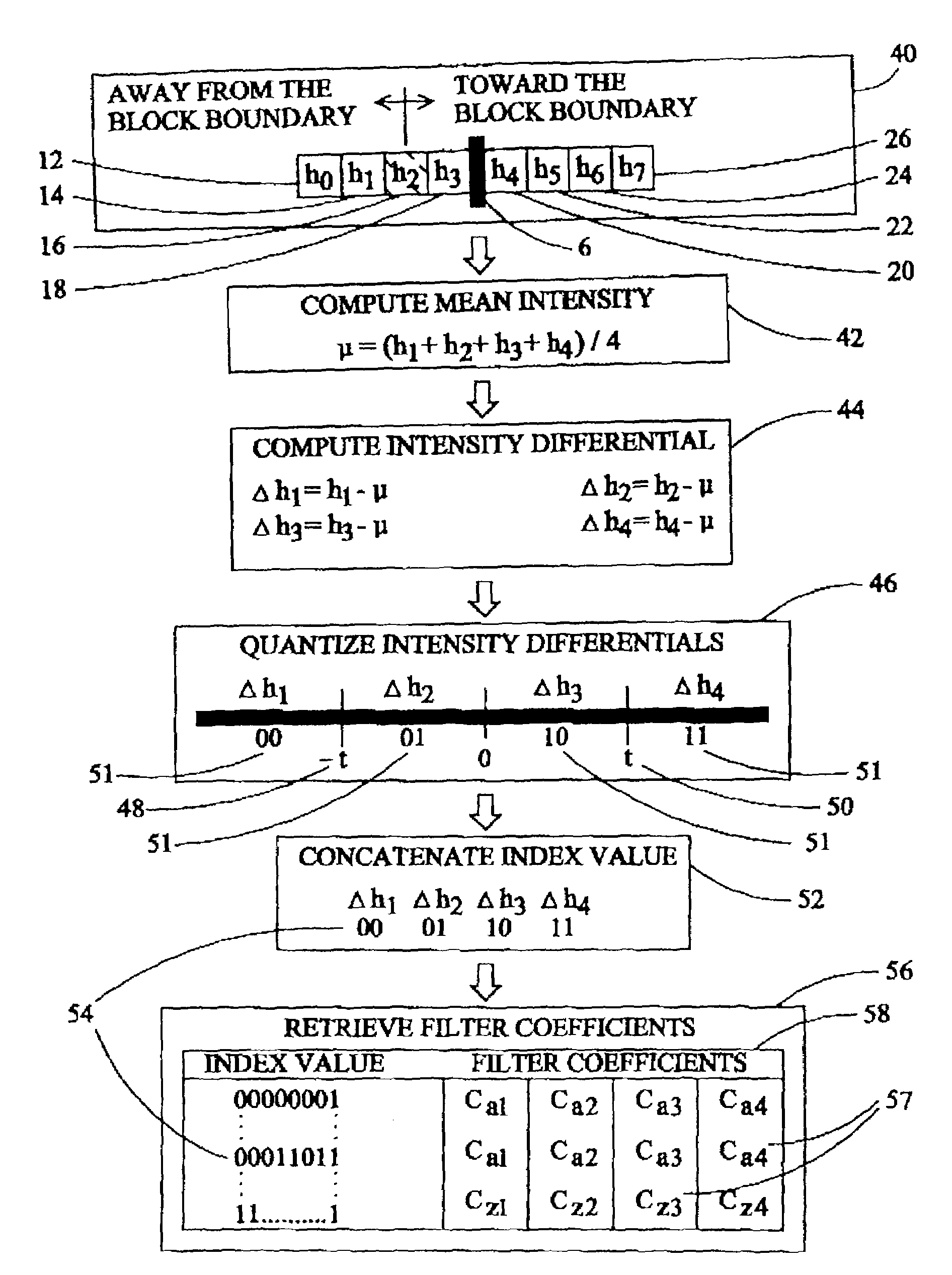
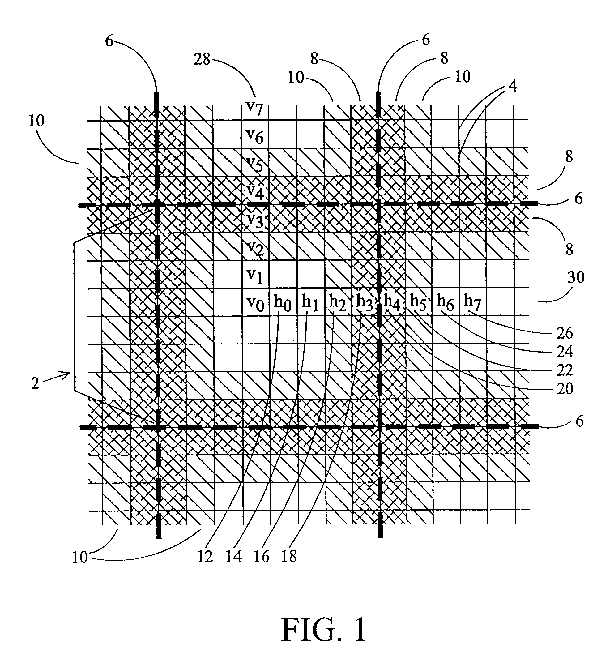
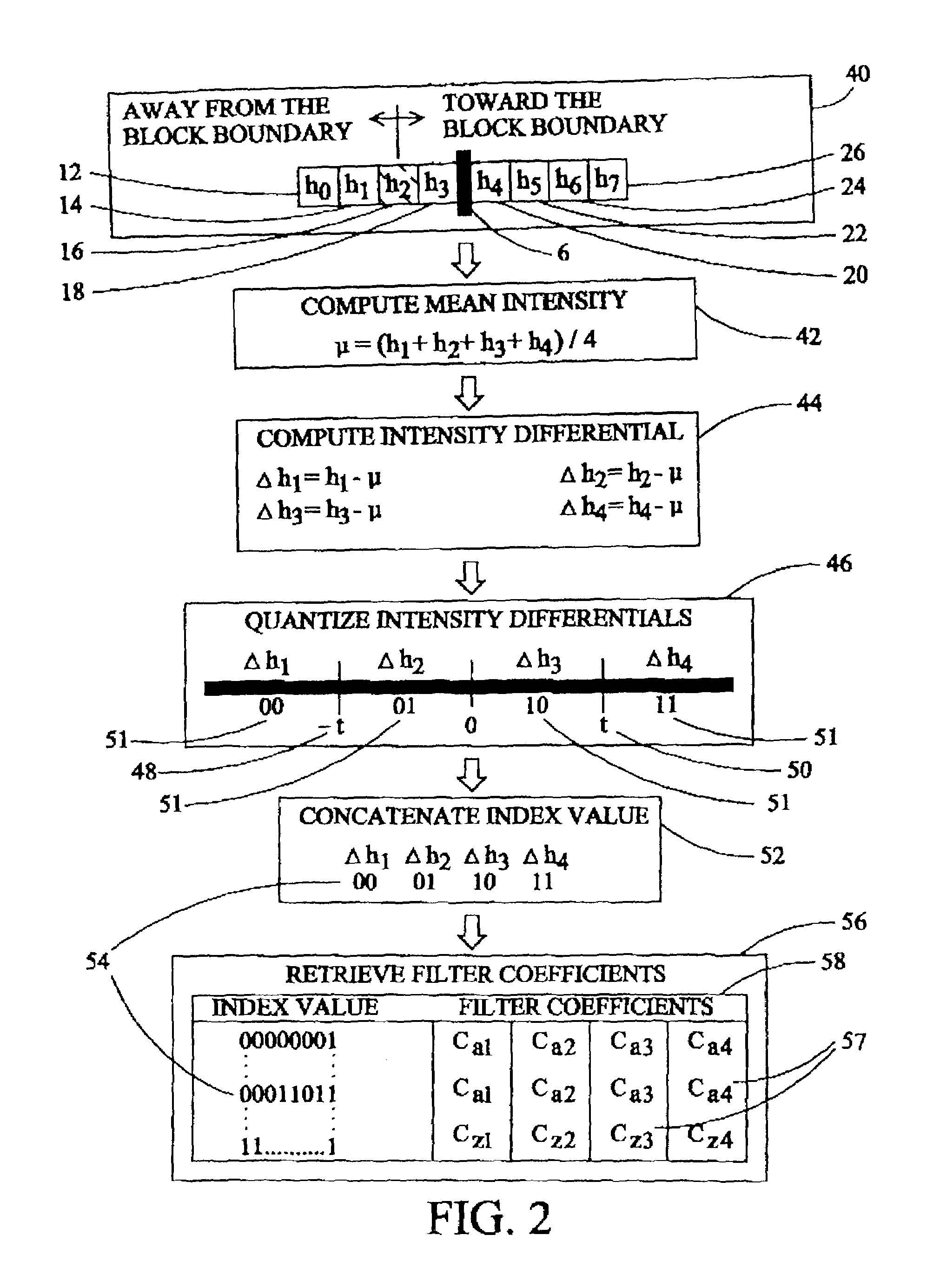
[0016]Many digital image compression schemes, such as the ISO “JPEG” specification for still images and the ISO “MPEG” specification for video, rely, at least in part, on block-based image compression. Referring to FIG. 1, the image is divided into a series of two dimensional areas or blocks 2, indicated by a bracket, and processing proceeds on a block-by-block basis. A common size processing block is eight pixels 4 in height by eight pixels 4 in width. Following transmission or storage, the image is reconstructed by reversing the process to decompress the image on a block-by-block basis. Data compression efficiency can be enhanced by discarding some information related to the image which is considered unnecessary for a viewer's appreciation of the reconstructed image. The discarded information is generally related to intermediate or higher frequency components of the data which describe minor details of the image. With block-by-block compression techniques, a part of the discarded ...


PUM


Abstract

Block boundary artifact reduction in decompressed digital images is accomplished by filtering the intensity of pixels in the vicinity of the block boundary. The filter utilizes filter coefficients selected from tables on the basis of the distribution of a scalar quantity describing the pixels neighboring the pixel to which the intensity adjustment is to be applied. The intensities of pixels at the boundary and one pixel removed from the boundary are adjusted. If interpolation pixels in each of neighboring blocks are of relatively constant intensity, the intensities of additional pixels, more remote from the boundary, are adjusted. Filter coefficients can be selected from different arrays for pixels on the boundary or removed from the boundary or if the pixel intensity adjustment is based on the intensities of pixels in a horizontal row or vertical column of interpolation pixels.

Description

BACKGROUND OF THE INVENTION[0001]The present invention relates to digital image reproduction and more particularly to a technique for reducing block boundary artifacts in digital images which have been subjected to block based image compression and decompression.[0002]In various applications, including high definition television and video conferencing systems, it is desirable to store and transmit images in a digital form. The amount of data generated by converting images from analog to digital form is so great that digital transmission and storage of images would be impractical if the data could not be compressed to require less bandwidth and data storage capacity. As a result, a number of techniques have been developed to compress the digital data representing an image and a video sequence.[0003]Several image and video compression techniques process digital image data by first dividing the image into 2-dimensional blocks. A common block size for block-based compression is an area ...

Claims


Application Information

Patent Timeline
Patent Type & Authority Patents(United States)
IPC IPC(8): G06K9/40G06T9/00H04N7/26H04N7/30
CPCH04N19/86H04N19/60
Inventor WESTERMAN, LARRY ALAN
Owner RAKUTEN GRP INC
Why Eureka
Try Eureka