Variable optical attenuator

Inactive Publication Date: 2006-07-11
INTEL CORP
View PDF23 Cites 11 Cited by
  • Summary
  • Abstract
  • Description
  • Claims
  • Application Information

AI Technical Summary

Benefits of technology

[0015]Variable optical attenuators in accordance with embodiments of the present invention may be implemented in optical cross-connect switches. In such embodiments, the ports and mirrors of the variable optical attenuator may also support switching functions in the optical cross-connect switch. Optical cross-connect switches are typically designed and operated to achieve minimum insertion loss for all optical signals couple

Problems solved by technology

Under such circumstances, the lower power wavelength channels might not be sufficiently amplified.
The additional hardwa

Method used


Image

  • Variable optical attenuator
  • Variable optical attenuator
  • Variable optical attenuator

Examples


Embodiment Construction

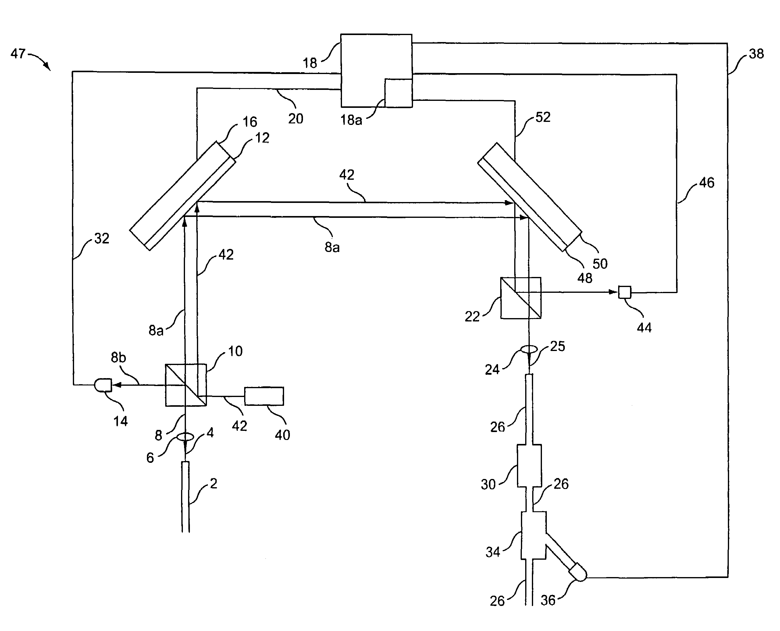
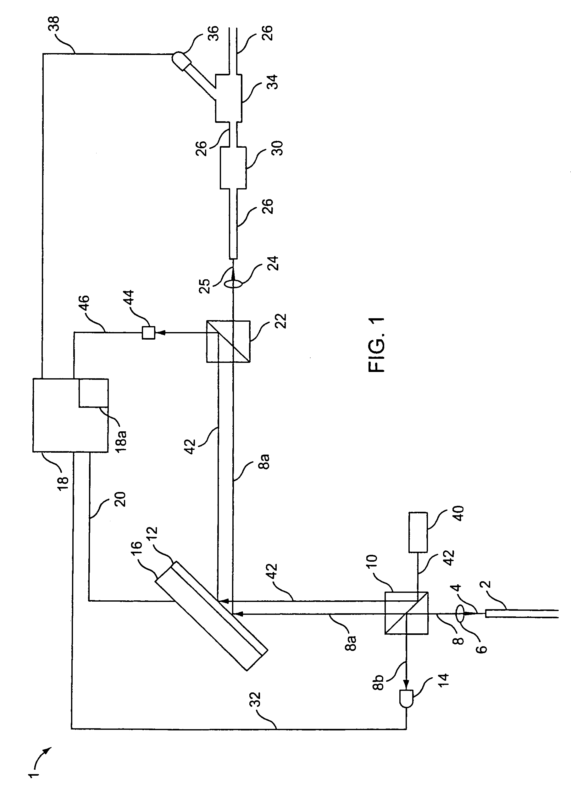
[0022]A variable optical attenuator in accordance with embodiments of the present invention variably attenuates light coupled into an optical fiber by controlled misalignment of one or more mirrors directing the light to the fiber. A number of embodiments will be described in which one or more optical signals are variably attenuated, and in which controlled misalignment of one or more mirrors is accomplished using, for example, measurements of the power of the attenuated optical signals or measurements of the position of control light beams separate from the optical signals to be attenuated.

[0023]Referring to FIG. 1, optical fiber 2 carries light to be attenuated by a controlled amount in a variable optical attenuator 1 in accordance with an embodiment of the present invention. As is conventional in DWDM, optical fiber 2 may carry light having a plurality of wavelengths. In one implementation, the light carried by optical fiber 2 has wavelengths near about 1310 nanometers (nm) or ab...


PUM


Abstract

A method of controllably attenuating a beam of light coupled into a port includes directing the beam of light against a mirror, and controlling an orientation of the mirror such that a predetermined fraction of the beam of light is coupled into the port. The predetermined fraction is less than a maximum fraction corresponding to optimal coupling of the beam of light into the port. The method may be implemented with a variable optical attenuator including a first port, a second port, a mirror located to direct light output by the first port to the second port, and a controller coupled to the mirror to align it such that the predetermined fraction of light is coupled into the second port. The method may also be implemented with an optical switch.

Description

CROSS REFERENCE TO RELATED APPLICATIONS[0001]This application is a Continuation of U.S. patent application Ser. No. 09 / 999,038, filed Oct. 24, 2001 now U.S. Pat. No. 6,754,431. This application is related to the following U.S. Patent Applications: U.S. patent application Ser. Nos. 09 / 999,878, 09 / 999,610, 09 / 999,705 and 09 / 779,189, entitled “A Microelectromechanical Mirror,” filed Feb. 7, 2001, all of which are assigned to the assignee of the present invention and incorporated herein by reference in their entirety.BACKGROUND OF THE INVENTION[0002]1. Field of the Invention[0003]The present invention relates to optical fiber cross-connect switching. More particularly, it relates lo load balancing in Dense Wavelength Division Multiplexing optical cross-connect systems.[0004]2. Description of the Related Art[0005]Associated with the information revolution is a need to increase by many orders of magnitude the rate of information transfer. This can be accomplished with optical fibers and ...

Claims


Application Information

Patent Timeline
IPC IPC(8): G02B6/35G02B6/26
CPCG02B6/266G02B6/3512G02B6/3594G02B6/359G02B6/3546
Inventor SUFLETA, ZBIGNIEWBRYZEK, JANUSZHARWIT, ALEXSMITH, JAMES HIGGINSHUANG, CHENG-CHUNGBAKIN, DMITRY VASILYNASIRI, STEVEN SAEED
Owner INTEL CORP
Why Eureka
Try Eureka