Flat top tunable filter with integrated detector

a detector and flat top technology, applied in the field of electric tunable optical filters, can solve the problems of poor adjacent channel rejection, high insertion loss, polarization independent devices, etc., and achieve the effect of minimizing overlap, maximum optical flatness, and minimal insertion loss

Inactive Publication Date: 2009-08-06
XTELLUS USA
View PDF98 Cites 1 Cited by
  • Summary
  • Abstract
  • Description
  • Claims
  • Application Information

AI Technical Summary

Benefits of technology

[0025]The disadvantages associated with the prior art may be overcome by a free space tunable filter that produces a passband output as a result of sequential processing by an array of narrowband tunable filters (NBTFs) each tuned to a slightly different frequency. The present invention is comprised of one or more stages, each having parallel reflective sidewall surfaces positioned in opposition to each other sandwiching an array of NBTFs. An input signal cascades through a stage bouncing off the sidewalls and the NBTFs which reflect a passband and transmit a transmission band, the compliment of the passband. Maximum optical flatness and minimum insertion loss are achieved by interleaving the NBTF center wavelengths to minimize the amount of overlap between any two sequential filters. Stages are cascaded to increase the device figure of merit and single stages are partitioned into multiple sectors that process a specific interleaved region of the bandwidth. Sector output includes group passband and group transmission band signals, where the group transmission signal couples to the input of the next sequential sector within that stage while the group passband signal couples to the input of a next cascaded stage. At the output of the final stage, all group passband signals are combined in a multiplexer and tapped with a partially transparent photodetector.

Problems solved by technology

Acoustic-optic devices provide rapid tuning in the microsecond range and complete blanking of the filter, however they are not polarization independent devices and suffer from poor adjacent channel rejection and high insertion loss.
The device did not produce a flat top output nor did it address temperature stability issues associated with robust control of liquid crystal devices.

Method used


Image

  • Flat top tunable filter with integrated detector
  • Flat top tunable filter with integrated detector
  • Flat top tunable filter with integrated detector

Examples


Embodiment Construction

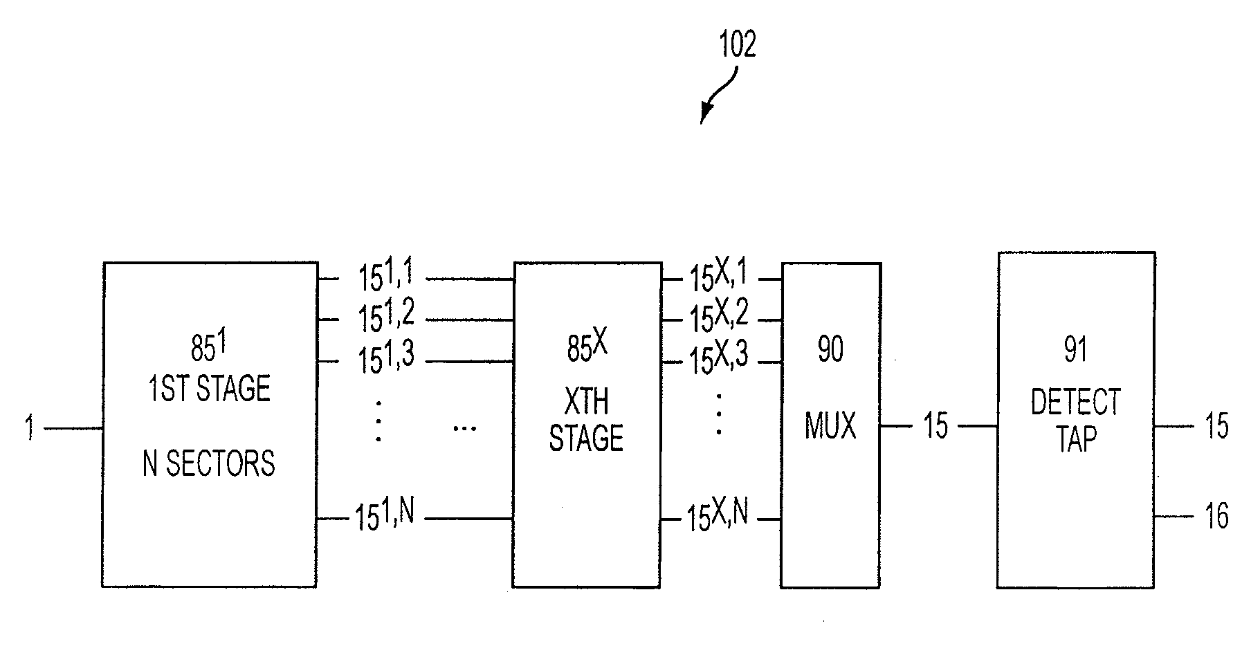
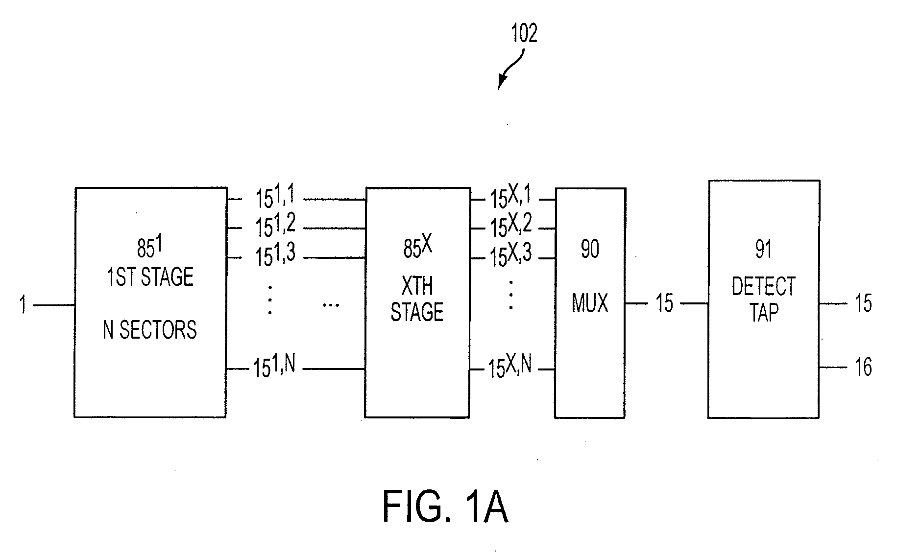
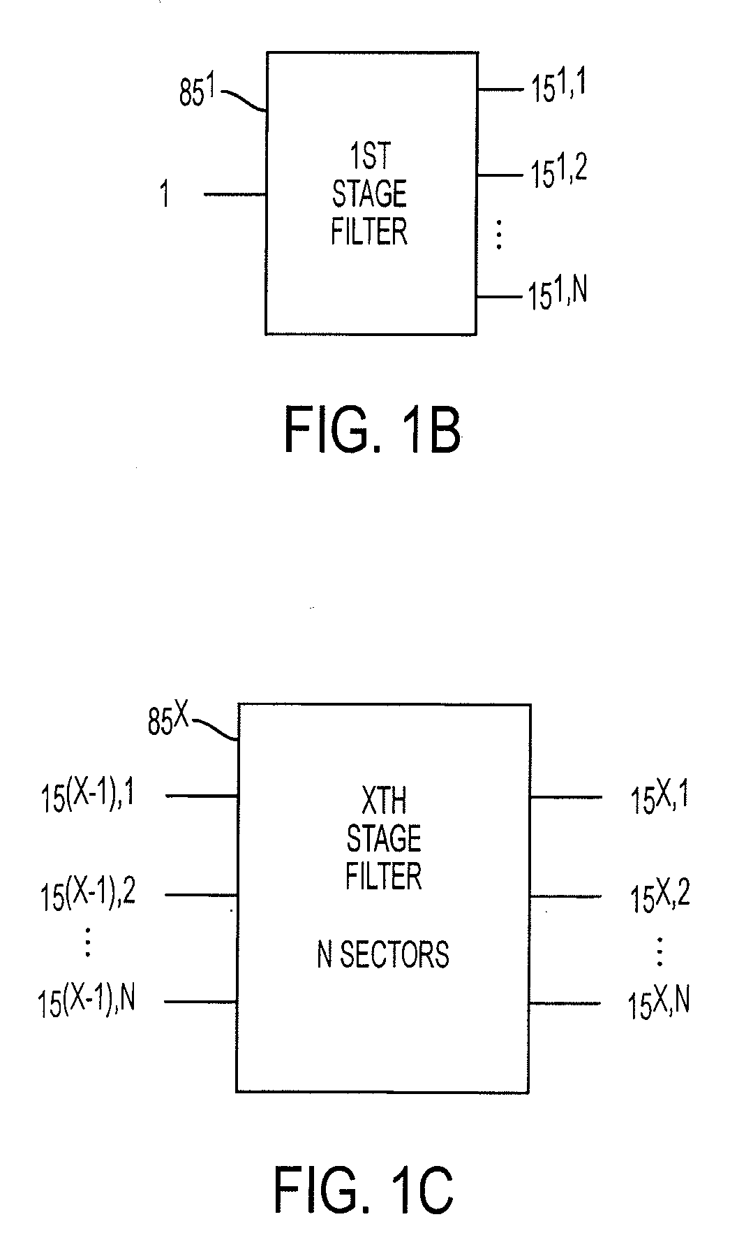
[0046]Throughout this application, like reference numbers as used to refer to like elements. For instance, the two substrates used to form the liquid crystal cell of the present invention are referred to throughout this applications as 110A and 110B. Those supporting elements and features of the invention that are distributed on each substrate and later combined may be referred to under their index reference for a particular substrate ′A, ′B or for simplicity sake, under the shared reference ′. Narroband tunable filter pixels used in the present invention are hereafter termed “NBTF pixels” and are individually addressed by reference 100stage, sector, sequence where sequence is the sequential order reference for any pixel. N is used throughout to designate sector number. X is used throughout to designate an arbitrary stage in the system. Reference 15stage,sector, is used throughout to index a group passband output in the system. Reference 85x is used throughout to index an arbitrary ...


PUM

PropertyMeasurementUnit
angleaaaaaaaaaa
diameteraaaaaaaaaa
center wavelength spacingaaaaaaaaaa

Abstract

A free space tunable filter produces a passband output as a result of sequential processing by an array of narrowband tunable filters (NBTFs) each tuned to a slIghtly different frequency. The present invention is comprised of one or more stages having multiple interleaved sectors and comprising an array of NBTFs having a masked outer surface reflective coating. Stages cascading is used to increase the device figure of merit and single stages are partitioned into multiple sectors that process a specific interleaved region of the bandwidth. Final stage output group passband signals are combined in a multiplexer and tapped with a partially transparent photodetector.

Description

CROSS-REFERENCE TO RELATED APPLICATIONS[0001]This application is a continuation of Ser. No. 10 / 607,855 filed Jun. 27, 2003, which is a continuation-in-part of the commonly assigned U.S. patent application titled “NARROW BAND TUNABLE FILTER WITH INTEGRATED DETECTOR”, filed on Jun. 2, 2003, Ser. No. 10 / 453,455 which is hereby incorporated herein by reference; and commonly assigned U.S. patent application titled, “MULTI-PIXEL LIQUID CRYSTAL CELL ARRAY”, filed on Mar. 17, 2003 and having Ser. No. 10 / 391,510 which is hereby incorporated herein. by reference; and commonly assigned U.S. patent application titled “LIQUID CRYSTAL OPTICAL PROCESSING SYSTEMS”, filed on Mar. 19, 2003 and having Ser. No. 10 / 394,400 which is hereby incorporated herein by reference; and commonly assigned U.S. patent application titled “LIQUID CRYSTAL CELL PLATFORM”, filed on Feb. 21, 2003 and having Ser. No. 10 / 371,235 which is hereby incorporated herein by reference.FIELD OF INVENTION[0002]This invention generall...

Claims


Application Information

Patent Timeline
Patent Type & Authority Applications(United States)
IPC IPC(8): G02F1/1335
CPCG02B6/12007G02B6/29358G02B6/29395G02B6/4215G02F2203/06G02F1/216G02F2201/307G02F2201/58G02F2203/055G02F1/01G02B6/4213
Inventor CAVANAUGH, SHANTI A.
Owner XTELLUS USA
Why Eureka
Try Eureka