
Mast for handling a coiled tubing injector

a technology for handling coiled tubing and injectors, which is applied in the direction of passenger handling apparatus, sealing/packing, and borehole/well accessories, etc., can solve the problems of causing safety hazards, significant damage to the wellhead, and easy failure of the cables used on the cranes that hoist the injector over the wellhead, so as to prevent the legs from collapsing

Inactive Publication Date: 2006-07-18
VARCO I P INC
View PDF24 Cites 75 Cited by
  • Summary
  • Abstract
  • Description
  • Claims
  • Application Information

AI Technical Summary

Benefits of technology

[0004]Unlike a conventional crane, a mast according to the invention raises and holds an injector or other oil field equipment over a wellhead using at least two telescoping arms. The equipment is placed between the arms, near a top end of the arms. Telescoping the arms raises the injector. Pivoting the mast moves the injector or other equipment over the wellhead. Such a mast need not utilize elements such as winches and cables to hoist the oil field equipment. Therefore, it can be made less susceptible to failure.
[0005]According to one aspect of a preferred embodiment of the invention, each arm is extended and retracted by use of a jackscrew. Each jackscrew preferably has a low pitch that makes it self-locking, thereby preventing collapsing of the legs under the weight of an injector if power is lost or interrupted. For arms with more than two segments, a lifting chain can be used to lift each additional segment. For example, in an arm with three segments, a lifting chain anchored at the top of the first segment extends up over a sprocket or pulley on top of the second segment and then back down to attach to a bottom of the third telescoping segment. The lifting chain pulls the third segment out of the second segment the second segment is pulled out of the first segment.

Problems solved by technology

Winches and cables used on the cranes that hoist the injector over the wellhead are prone to failure.
Failure of any of these elements can result in significant damage to the wellhead and creates a safety risk.

Method used


Image

  • Mast for handling a coiled tubing injector
  • Mast for handling a coiled tubing injector
  • Mast for handling a coiled tubing injector

Examples


Embodiment Construction

[0023]Like numbers refer to like elements in the following description.

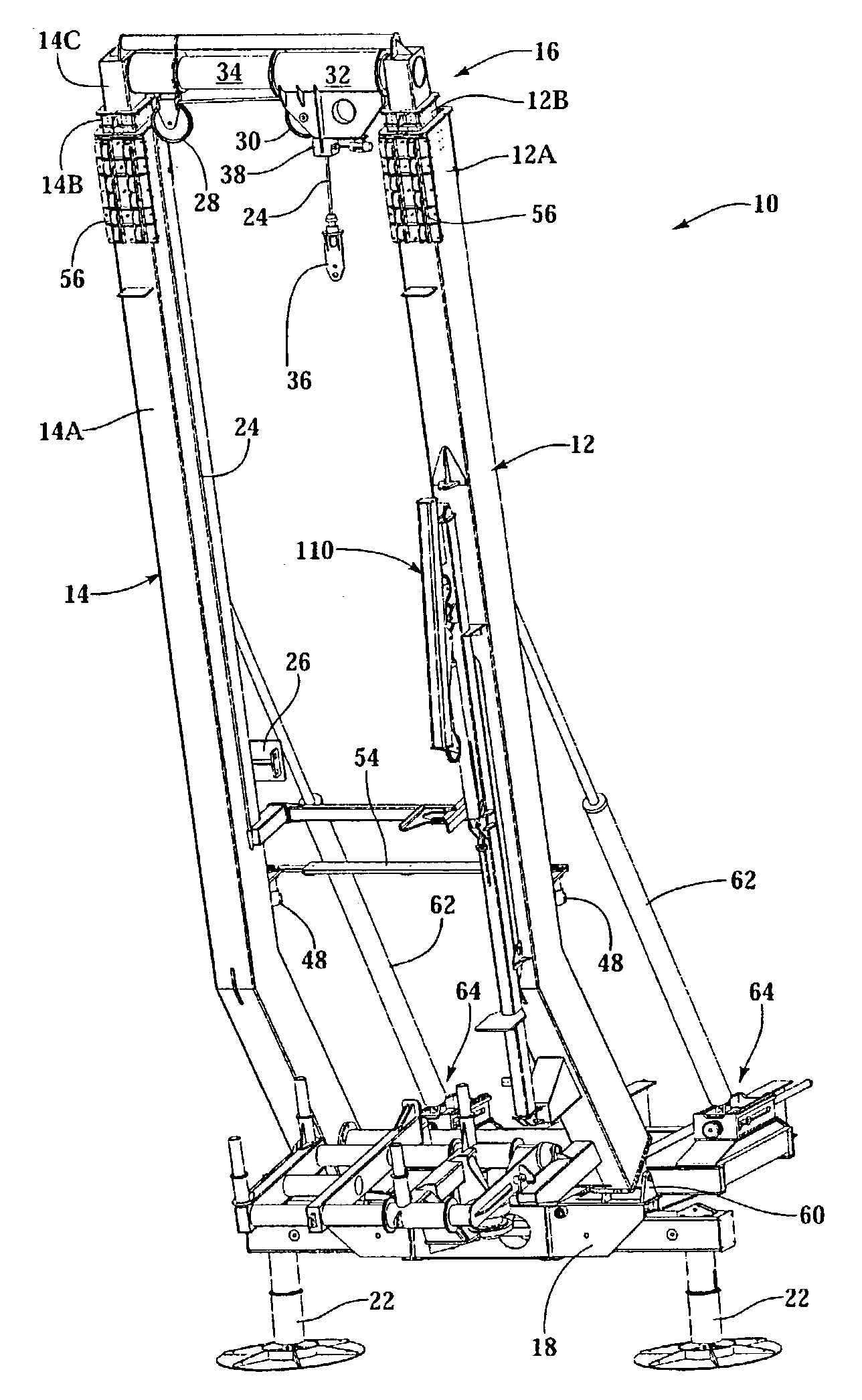
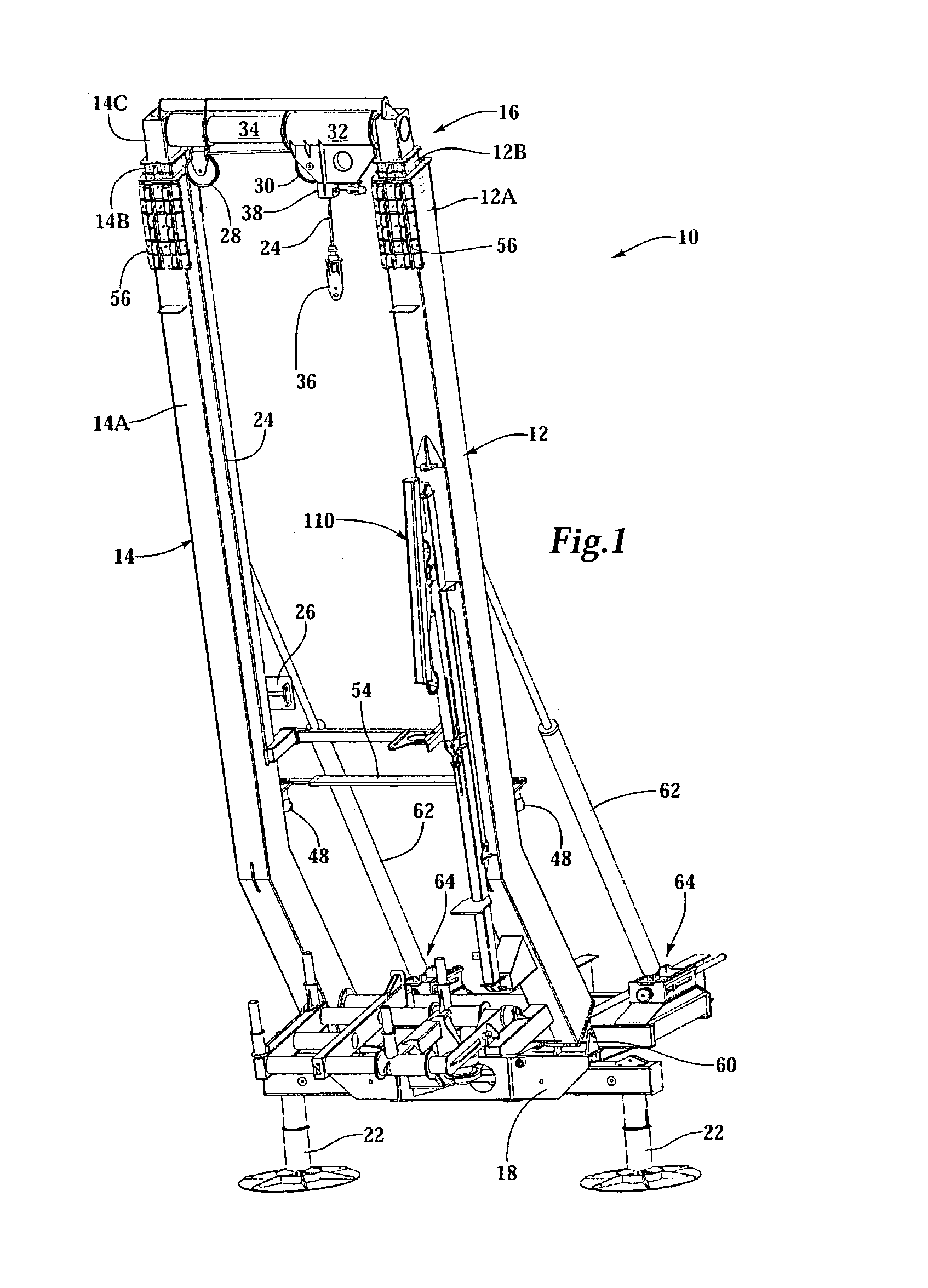
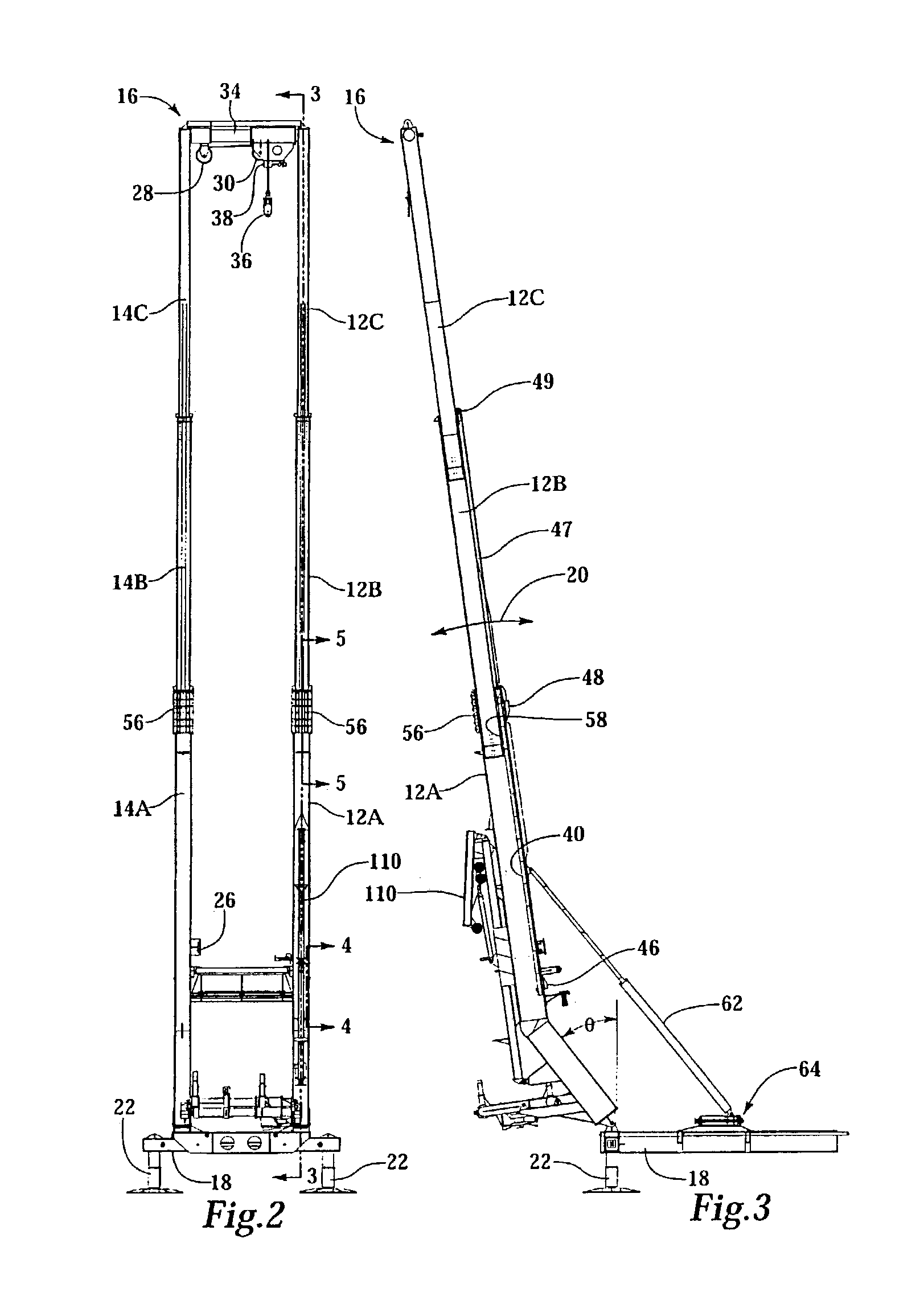
[0024]FIGS. 1–3 are various views of an exemplary embodiment of a mast assembly for suspending coiled tubing injectors and other equipment over a wellhead. In this embodiment, mast assembly 10 includes two generally parallel telescoping arms 12 and 14. Each arm includes a plurality of telescoping segments, labeled 12A, 12B and 12C and 14A, 14B and 14C, respectively. The arms are shown fully retracted in FIG. 1: segments 12C, and 14C are drawn or received inside segments 12B and 14B, respectively; and segments 12B and 14B are drawn into segments 12A and 14A, respectively. The mast assembly is shown in a fully extended position in FIGS. 2 and 3.

[0025]Cross member assembly 16 extends between, and is connected to, segments 12C and 14C so that the distance from the base of the mast assembly to the cross member assembly increases as the mast assembly telescopes outwardly. Coiled tubing injector or other equipment to be...


PUM


Abstract

A mast for lifting and suspending over a wellhead a coiled tubing injector and blow out preventer is pivotally mounted on a rear portion of a truck. The mast has two side-by-side telescoping legs that extend and retract synchronously. When in a retracted position, the blow out preventer and coiled tubing injector are attached to the mast, between the legs, and legs of the mast extended to lift the equipment.

Description

CROSS REFERENCE TO RELATED APPLICATIONS[0001]This application claims priority to related provisional patent application No. 60 / 334,868 entitled, “Mast for Handling a Coiled Tubing Injector” filed Oct. 30, 2001, which is incorporated herein by reference.BACKGROUND OF INVENTION[0002]Coiled tubing injectors are used to run in and out of well bores continuous pipe. Continuous pipe is referred to as coiled tubing because it is stored on large reel. Though coiled tubing can be used for drilling operations, it is ideal for servicing existing wells. It can be run in and out of the well bore much faster than conventional, jointed pipe. Furthermore, no complex drilling rig or other structure needs to be erected at the well. A crane is transported to the site, along with the blow out preventer, coiled tubing and coiled tubing injector, on the back of a truck. The crane is used to hoist and hold a blow out preventer and coiled tubing injector over the wellhead during servicing. With a conventio...

Claims


Application Information

Patent Timeline
Patent Type & Authority Patents(United States)
IPC IPC(8): E21B19/086E21B19/02B66C19/00B66C23/60B66C23/687E21B15/00E21B19/22
CPCB66C19/00E21B19/22E21B15/00B66C23/60B66C23/04E21B19/00E21B19/24
Inventor MCCULLOCH, DAVID W.LU, MIKE XIAOLEI
Owner VARCO I P INC
Learn More