Earth scraper with track apparatus

a track apparatus and earth scraper technology, applied in mechanical machines/dredgers, shock absorbers, drags, etc., can solve the problems of affecting the wheels of earth moving vehicles, ruts which affect the wheels of hauling roads, and the prepared condition is difficult to loosen or level, so as to reduce the compaction of earth, increase traction, and reduce the effect of earth compaction

Inactive Publication Date: 2006-07-18
ATI TECH INC
View PDF35 Cites 36 Cited by
  • Summary
  • Abstract
  • Description
  • Claims
  • Application Information

AI Technical Summary

Benefits of technology

[0012]Another object of the invention is to provide a scraper which eliminates or reduces vibration and / or bouncing during transport.
[0031]The scraper may also be of the self-loading pan type in which the scraper comprises a tractor section and a scraper section; the scraper section including the blade, receiving area, axle and track apparatus, and the tractor section including a pair of ground-engaging wheels. Movement of such a scraper may rely on the ground-engaging wheels of the tractor section when the ground-engaging wheels are powered, or the rotatable axle and track apparatus of the scraper section may be powered, or both sections may be powered. In certain embodiments, the ground-engaging wheels are converted into track apparatus as well. To improve traction, the flexible tracks on the track apparatus of the scraper section may be installed backwards, particularly in pull-type applications.

Problems solved by technology

Oftentimes, the soil to be prepared is in a packed condition that is difficult to loosen or level.
Because of the tremendous amount of weight carried by loaded earth moving vehicles, the haul road undergoes extreme compression.
Such differences in compression cause ruts which impact the wheels of the earth moving vehicles during transport.
The bounce of the vehicles, in turn, pumps the road beyond the initial rut and causes further rutting until virtually the entire road is rutted from the work site to the dump site.
For instance, an initial rut causes a vehicle to bounce and pump the haul road beyond the rut.
Such rutting typically requires earth moving vehicles to travel at lower speeds than is preferred which causes a substantial increase in the amount of time needed to complete an earth moving operation.
This problem may be encountered even when traveling on a smooth roadway without variable initial earth compaction because the vibration inherent in the use of motorized vehicles is often translated into a bouncing motion by the scraper's wheels.
When dealing with very heavy equipment and loads, such small vibration quickly leads to a large bouncing force which is able to pump the roadway and cause rutting.
Another problem is frequently encountered by scrapers which are used on hill sides or other uneven terrain.
Often scrapers employed in such use slide down the hillside or even roll over during operation.
Sliding is typically caused by the heavy load of the scraper coupled with the poorer traction of the scraper's wheels compared to the towing device's wheels or the tractor portion's wheels.
Rolling over usually occurs when the uphill wheel of the scraper encounters a bump or rut which causes the uphill tire to bounce.
The upward shift in weight causes the center of gravity to shift upward and results in the scraper rolling over, especially when the scraper is holding a large amount of weight.
Another problem faced by scrapers is the uniform compaction of earth under the scraper wheels in the direction of travel.
Use of scrapers along a path often results in grooves in which the scraper's wheels ride.
Eventually such grooves become so deep that the underside of the scraper hits the earth between the grooves and the scraper becomes stuck.
This problem is aggravated when working in wet areas where a loaded scraper may sink into the earth on its first pass across a path.
Often a fully loaded scraper must be unloaded before it can be removed from its stuck position, resulting in a large delay in completing the job.
As can be seen, regardless of the type of scraper utilized, several problems are encountered when removing and transporting large amounts of earth.

Method used


Image

  • Earth scraper with track apparatus
  • Earth scraper with track apparatus
  • Earth scraper with track apparatus

Examples


Embodiment Construction

[0059]Prior track apparatus for vehicles are disclosed in U.S. Pat. Nos. Re36,284 (Kelderman), U.S. Pat. No. 5,829,848 (Kelderman), U.S. Pat. No. 6,536,854 (Kahle et al.), 6,543,861 (Kahle et al.), U.S. Pat. No. 6,543,862 (Kahle et al.) and U.S. Pat. No. 6,557,953 (Kahle et al.) assigned to the assignee of the present invention and incorporated herein by reference.

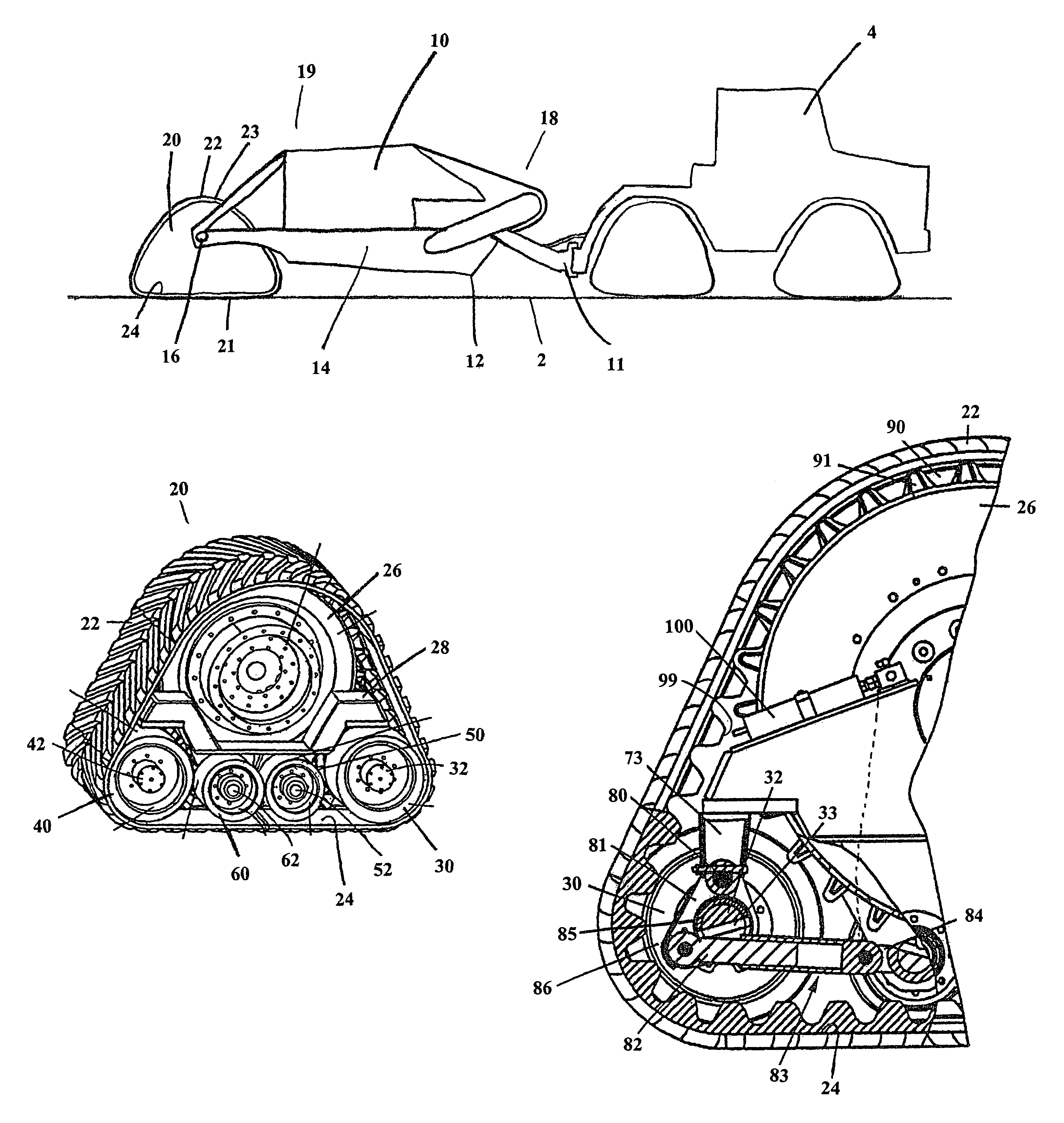
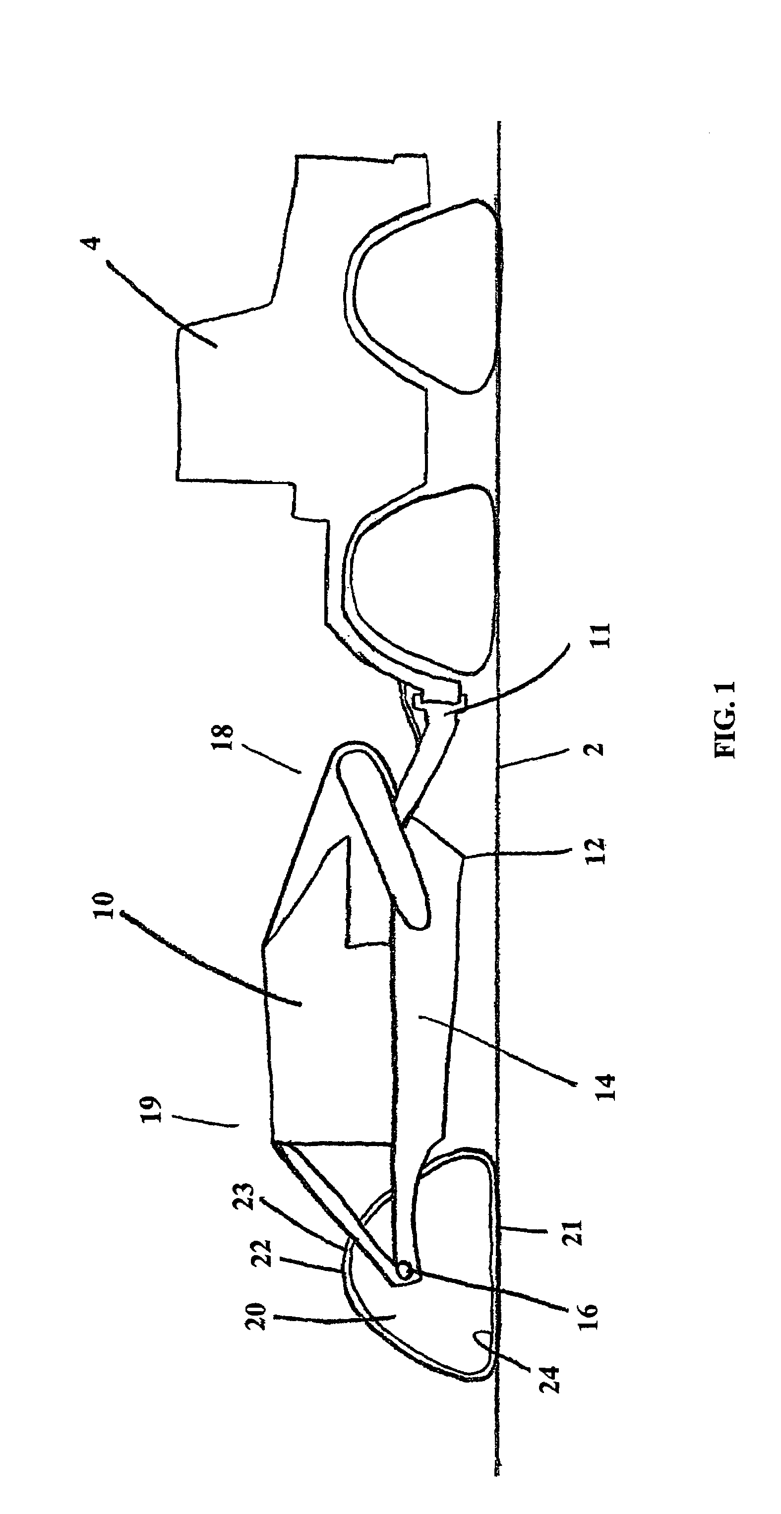
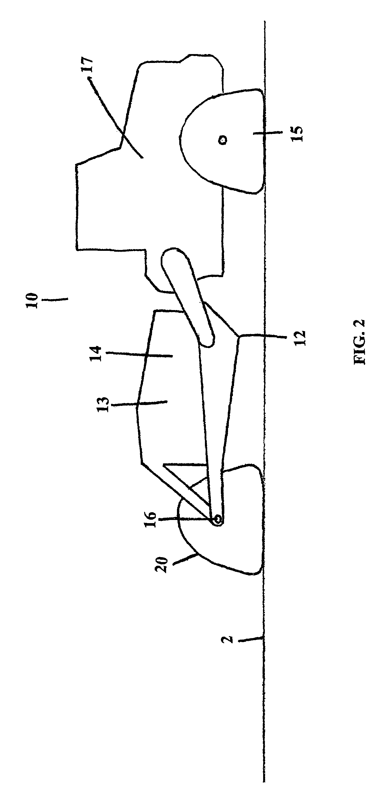
[0060]Referring to FIG. 1, a scraper in accordance with the present invention is generally designated by the reference numeral 10. Scraper 10 includes a blade 12, receiving area or bin 14, rotatable axle 16 and track apparatus 20. Track apparatus 20 includes flexible track 22 which has an upper length 23 and lower length 21 for engaging the ground. Flexible track 22 includes an inner surface 24. As shown rotatable axle 16 and track apparatus 20 are positioned at the second end 19 of scraper 10 while a hitch 11 is positioned at first end 18. Hitch 11 provides for connection to a towing vehicle such as tractor or prime mover...


PUM


Abstract

An earth working scraper for use removing and transporting earth is disclosed. The scraper includes a scraper blade for scraping earth from a ground surface, a receiving area located near the blade for receiving earth scraped from the ground surface by the blade, a rotatable axle for providing transportation of the scraper connected with respect to the blade and receiving area, and a track apparatus connected with respect to the rotatable axle. The track apparatus may include a continuous flexible track having an upper length and a ground-engaging lower length and including an inner surface, an axle wheel mountable to the rotatable axle for rotational movement therewith, the axle wheel engaging the inner surface of the flexible track along the upper length to drive the flexible track in response to rotation of the axle, and a frame for mounting the axle wheel.

Description

FIELD OF THE INVENTION[0001]This invention relates generally to earth working equipment. More specifically, the invention pertains to scraping devices used to level or smooth a ground surface by scraping and / or spreading earth.BACKGROUND OF THE INVENTION[0002]In the construction industry, the need for manipulating soil and other bases for construction is frequently encountered. This need typically occurs in the construction of buildings, paved roads and parking lots and other improvements. Oftentimes, the soil to be prepared is in a packed condition that is difficult to loosen or level. Therefore, mechanical scrapers of different designs have been developed to scrape, level or otherwise prepare earth for construction.[0003]Such use requires that scrapers remove and transport large amounts of earth. Scrapers are typically wheeled and may be towed or self-propelled. Either type of scraper includes a pan which may be lowered to be brought into contact with the earth or raised to be bro...

Claims


Application Information

Patent Timeline
Patent Type & Authority Patents(United States)
IPC IPC(8): E02F3/76A01B15/00A01B23/00A01B31/00A01B35/20A01B39/20E02FE02F3/64E02F5/10E02F9/02
CPCA01B31/00B62D55/0885B62D55/10B62D55/1125E02F9/02E02F3/64E02F3/6454E02F3/65E02F5/08B62D55/305F16F9/065
Inventor JUNCKER, KENNETH J.
Owner ATI TECH INC
Why Eureka
Try Eureka