Beverage forming and dispensing system

a technology for forming and dispensing systems and beverages, applied in liquid handling, process and machine control, instruments, etc., can solve the problems of valves that require periodic cleaning, take a significant amount of time, and require significant cost, so as to improve the quality of dispensed beverages

Inactive Publication Date: 2006-07-18
PEPSICO INC
View PDF53 Cites 90 Cited by
  • Summary
  • Abstract
  • Description
  • Claims
  • Application Information

AI Technical Summary

Benefits of technology

[0009]The present invention can provide a system for improving the quality of a dispensed beverage from a carbonated beverage forming and dispensing system.
[0010]The present invention can also provide a system for controlling the concentrate and water supplies in a beverage forming and dispensing system to control the quality of a dispensed beverage.
[0011]The present invention can still further provide a system that can change the control of the brixing ratio to that corresponding to any one of a number of concentrates.
[0012]In addition, the present invention can provide a system that can dispense water and concentrate at a desired ratio throughout its lifetime without maintenance or adjustment.
[0013]Still further, the present invention can provide a system including a nozzle assembly in which the internal components of the nozzle assembly can be kept free of incursion of liquid.

Problems solved by technology

After adjusting the carbonator, the technician must then readjust the water-to-syrup ratio of each valve, which can take a significant amount of time and result in significant cost.
Further, such valves require periodic cleaning.
Other known devices provide means to regulate syrup flow only, but only for a very limited set of operational conditions.

Method used


Image

  • Beverage forming and dispensing system
  • Beverage forming and dispensing system
  • Beverage forming and dispensing system

Examples


Embodiment Construction

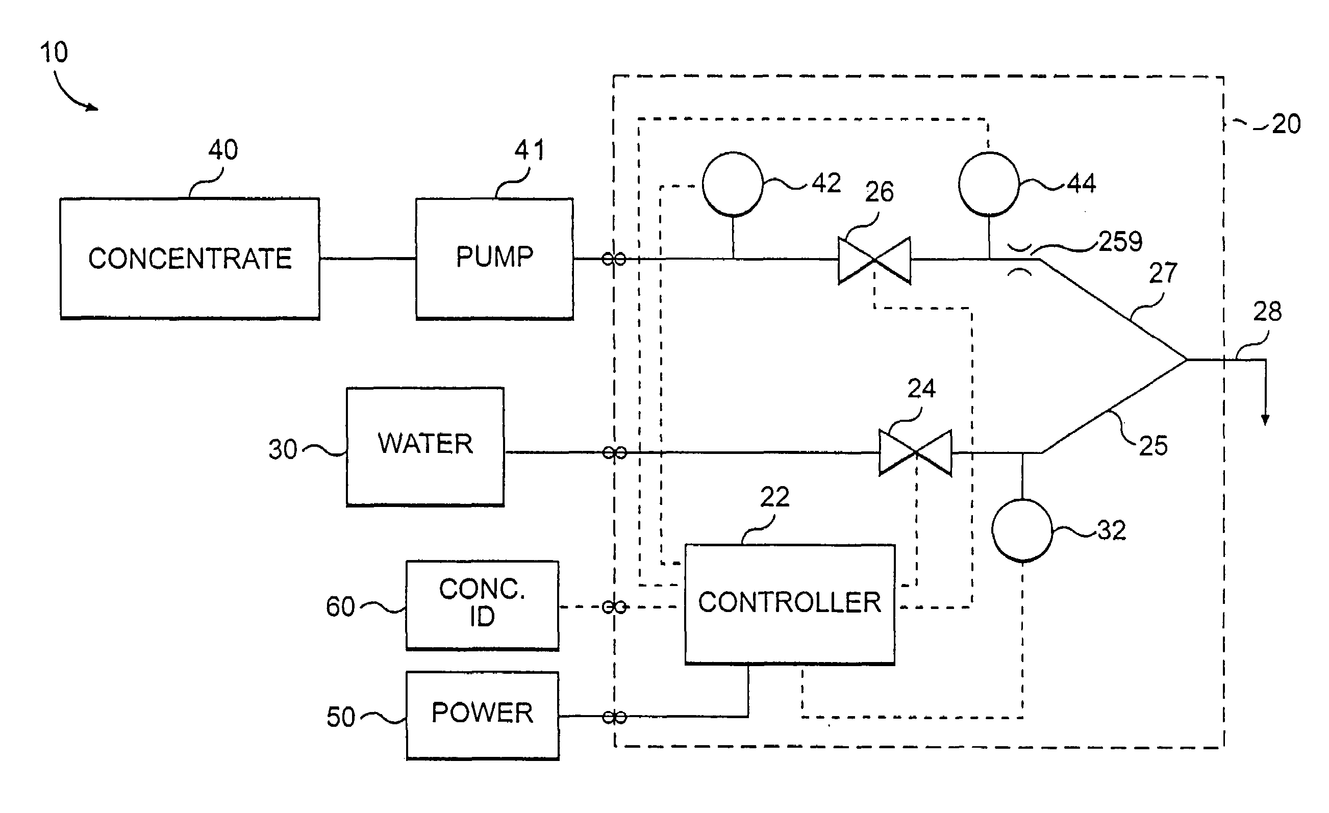
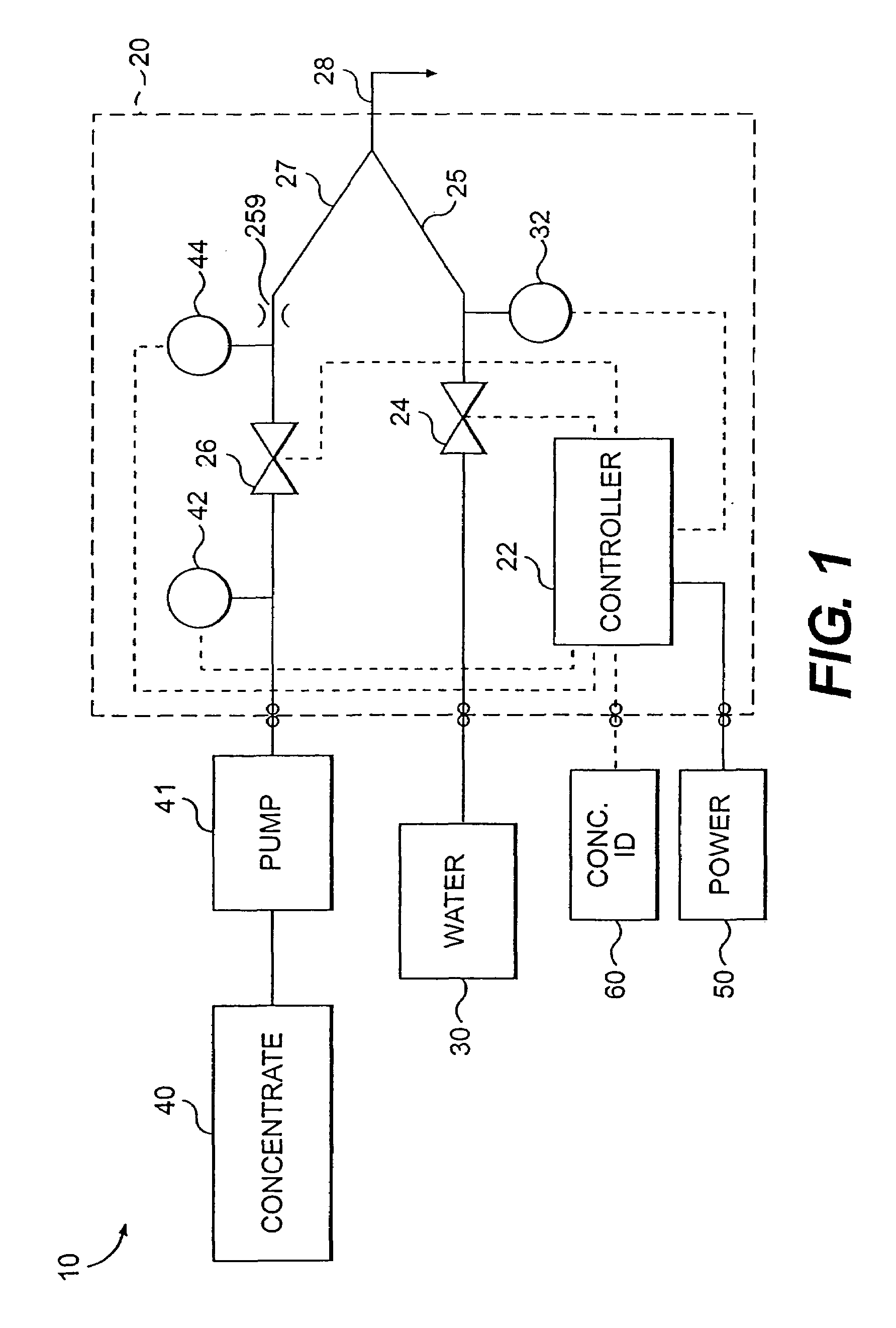
[0026]FIG. 1 depicts a schematic diagram of the beverage forming and dispensing system 10 according to the present invention. System 10 includes a valve assembly 20, a carbonated water supply 30, a syrup or concentrate supply 40 and a power supply 50. Valve assembly 20 is mountable on a well-known base or tower (not shown), through which the concentrate, carbonated water and power is supplied.

[0027]Valve assembly 20 includes a controller 22, such as a microprocessor, for controlling the flow rate of the carbonated water and concentrate at a predetermined ratio or brix. Microprocessor 22 is powered through power source 50, which can include transformers to provide a DC voltage. Carbonated water source 30 can include a well-known carbonator tank and a cold plate (unshown) to chill the water supply, if desired. Concentrate supply 40 can be in the form of a bag-in-box type and the concentrate is typically pumped by a concentrate pump 41.

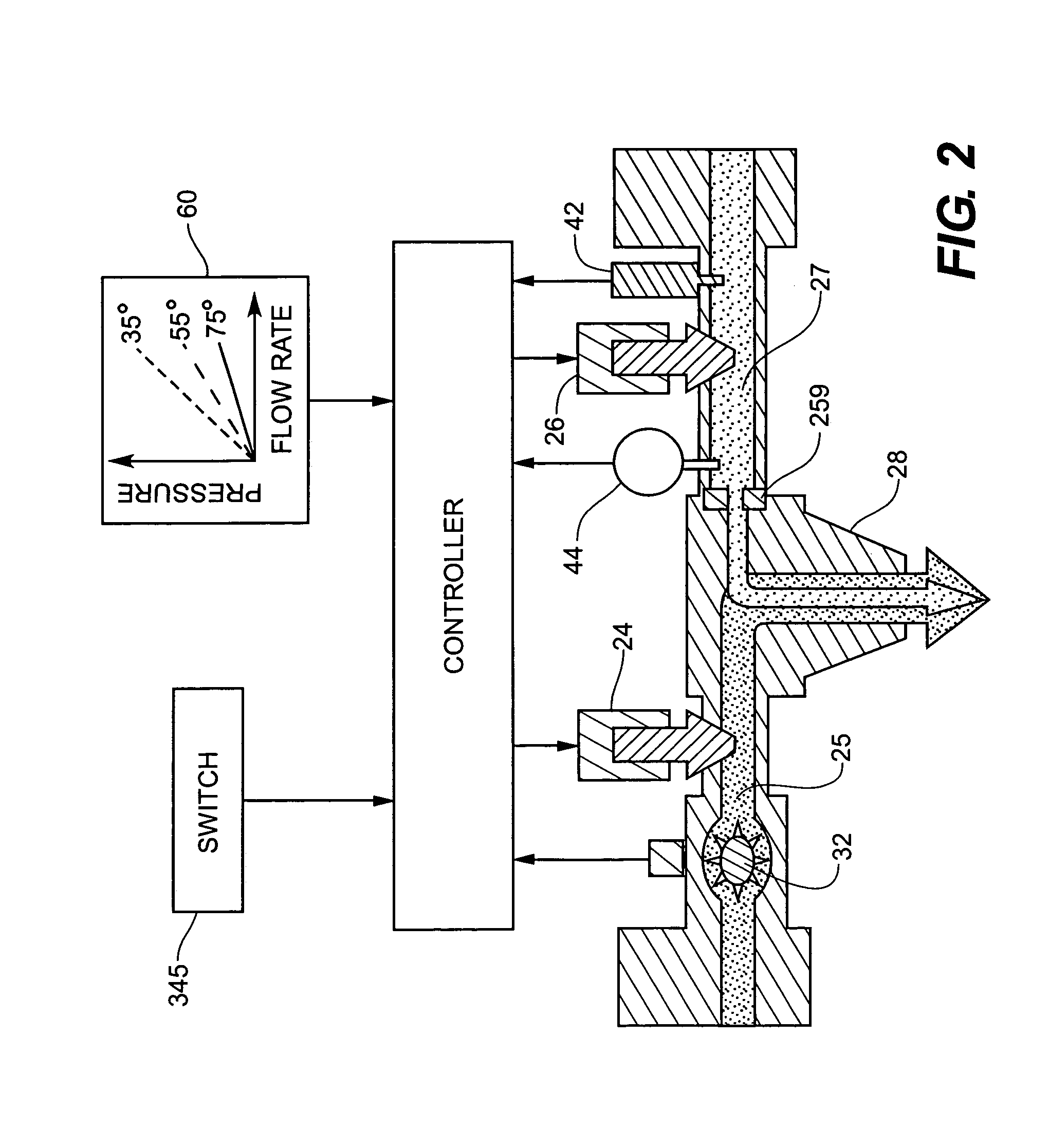
[0028]Valve assembly 20 includes two flow control ...


PUM


Abstract

A beverage dispensing system includes separate valves for controlling the flow rate of a diluent and a concentrate. Various concentrates of different viscosities can be used and the selected concentrate is identified. The flow rate of the concentrate is determined based on temperature and pressure and on information related to the identified concentrate. The valves are controlled so that the concentrate and diluent reach target flow rates. The target flow rates satisfy a target ratio of diluent to concentrate. If the actual flow rates cannot reach the target flow rates, then the target flow rates are modified to satisfy the target ratio. The structure of the concentrate valve is designed to accommodate proportional metering of any one of the various concentrates.

Description

[0001]This application claims the benefit of U.S. Provisional Patent Application No. 60 / 380,849, filed May 17, 2002.BACKGROUND OF THE INVENTION[0002]1. Field of the Invention[0003]The present invention relates to beverage forming and dispensing systems. More particular, the present invention relates to beverage forming and dispensing systems for effectively preparing a beverage mixture from concentrate, and even more particularly to beverage forming and dispensing systems for effectively monitoring and controlling the quality of a post-mix product. The present invention further relates to a dispensing valve assembly of a single design that can be used with any of various types of concentrates.[0004]2. Description of the Related Art[0005]Beverages formed from concentrate are enjoyed around the world. An important advantage of forming a beverage from a concentrate is that only the concentrate need be shipped to the dispensing site; any available water supply at the site can be used to...

Claims


Application Information

Patent Timeline
Patent Type & Authority Patents(United States)
IPC IPC(8): B67D5/56B67D7/08B67D1/00B67D1/08B67D1/12B67D7/74
CPCB67D1/0032B67D1/0085B67D1/0855B67D1/1218B67D1/1243B67D1/1295B67D1/1455B67D1/1222B67D2001/0811G05D11/132
Inventor BETHUY, TIMOTHY W.BLACK, WILLIAM J.CAHILL, BRIAN T.NELSON, ANDREW D.MEHN, PETER D.
Owner PEPSICO INC
Why Eureka
Try Eureka