

Sheet metal scale removing water jet process
a technology of water jet and sheet metal, which is applied in the direction of chemistry apparatus and processes, cleaning using liquids, manufacturing tools, etc., can solve the problems of substantial area and environmental hazards of acid used in the acid bath of sheet metal
- Summary
- Abstract
- Description
- Claims
- Application Information
AI Technical Summary
Benefits of technology
Problems solved by technology
Method used
Image

Examples
Embodiment Construction
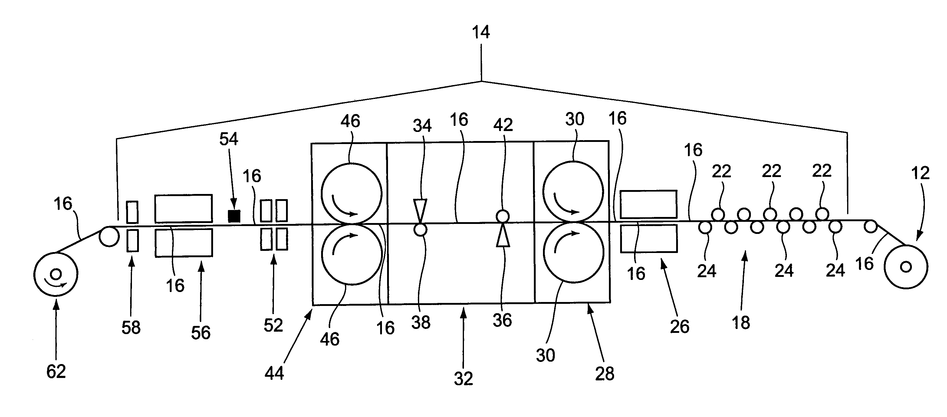
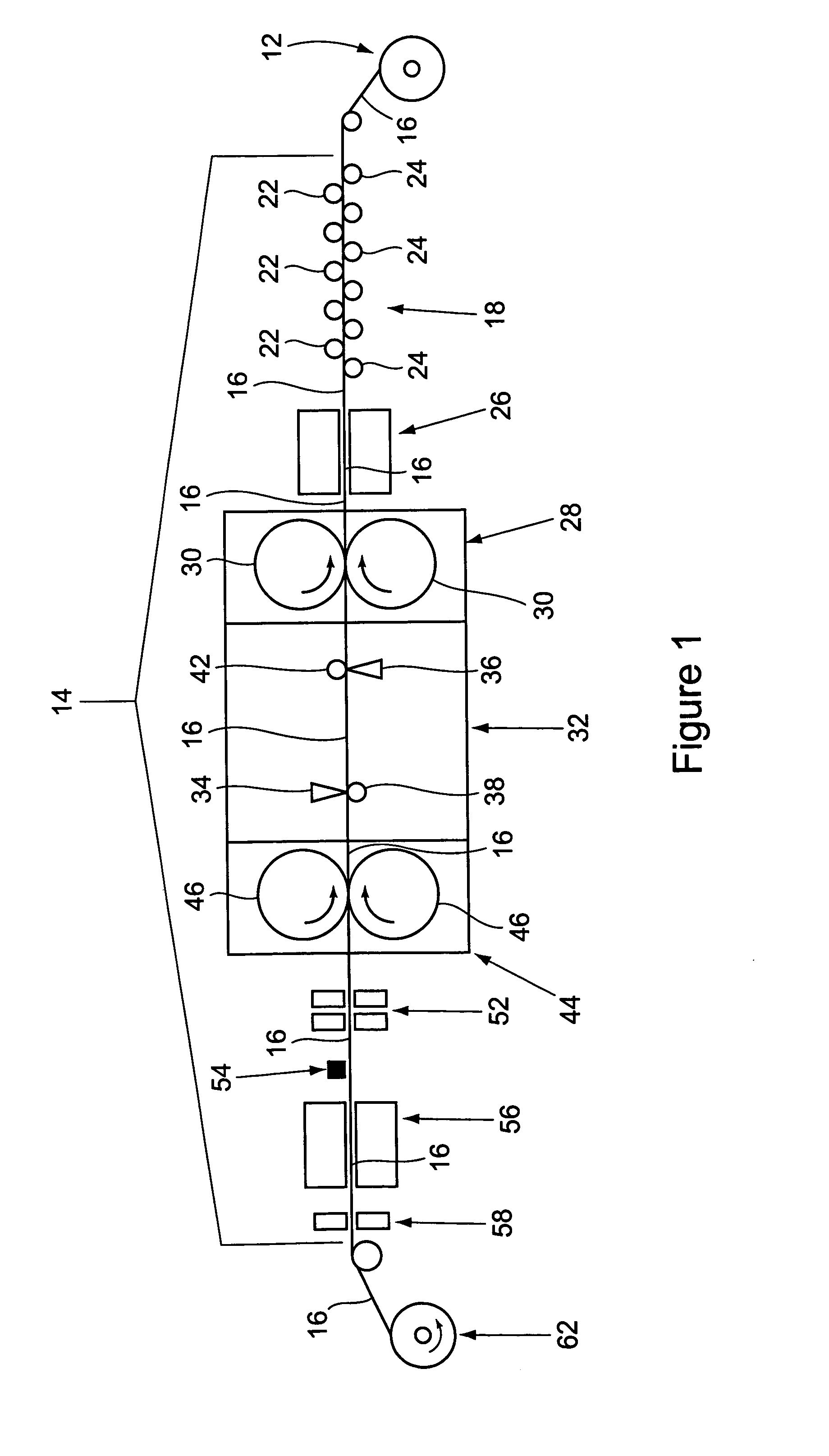
[0022]FIG. 1 shows a schematic representation of the apparatus of the invention that is used to perform the method of the invention in removing scale from the surfaces of processed sheet metal. As will be explained, the sheet metal moves from right to left through the apparatus shown in FIG. 1. The component parts of the apparatus to be described and shown in FIG. 1 are the preferred embodiment of the invention. It should be understood that variations and modifications could be made to the preferred embodiment to be described without departing from the intended scope of protection provided by the claims of the application.
[0023]Referring to FIG. 1, a roll of previously processed sheet metal (for example hot rolled sheet metal) 12 is positioned adjacent the apparatus 14 for supplying a length of sheet metal 16 to the apparatus. The roll of sheet metal 12 may be supported on any conventional device that functions to selectively uncoil the length of sheet metal 16 from the roll 12 in a...
PUM
| Property | Measurement | Unit |
|---|---|---|
| pressure | aaaaa | aaaaa |
| length | aaaaa | aaaaa |
| temperature | aaaaa | aaaaa |
Abstract
Description
Claims
Application Information