
Range finder for measuring three-dimensional geometry of object and method thereof

a three-dimensional geometry and range finder technology, applied in the field of three-dimensional image capture technique, can solve the problems of deterioration of measurement accuracy, difficulty in determining which one of the projected stripe light beams corresponds to the captured stripe image, and render computation of a range impossible, so as to prevent deterioration of measurement

Inactive Publication Date: 2006-07-18
FUJIFILM BUSINESS INNOVATION CORP
View PDF16 Cites 16 Cited by
  • Summary
  • Abstract
  • Description
  • Claims
  • Application Information

AI Technical Summary

Benefits of technology

The present invention provides a three-dimensional image capturing technique that prevents deterioration of measurement caused by texture or stain on an object. The invention includes a range finder for measuring the geometry of an object, a first image capturing unit for capturing an image reflected from the object, a second image capturing unit for capturing an image reflected from the object, an identical principal point arrangement unit for arranging the projector unit and the first image capturing unit at the position of an optically identical principal point, and an imaging optical system shared between the projector unit and the first image capturing unit. The invention also includes a method for measuring the geometry of an object using a projector unit, first and second image capturing units, and an identical principal point arrangement unit. The invention provides a three-dimensional image camera that enables measuring the geometry of an object with improved accuracy and efficiency.

Problems solved by technology

When the object has a texture (e.g., a color or a pattern), difficulty is encountered in determining a range.
This poses difficulty in determining which one of the projected stripe light beams corresponds to the captured stripe image.
Therefore, an erroneous correspondence occurs, which in turn renders computation of a range impossible.
However, when an optical system of the projection system and an optical system of the image capturing system are configured to be independent of each other as mentioned above, laborious tasks, such as those which will be mentioned below, arise when zoom ratios of the optical systems are desired to be changed in accordance with the size of an object.
Therefore, very complicated tasks arise, including re-adjustment of the projection and image capturing systems, which have once been arranged in accordance with the shift, such that the optical systems of the projection and image capturing system come to an identical optical point, thereby causing a problem of deterioration of usability.
Another problem is that the characteristic of the identity of the optically principal points of the projection system and the image capturing system is realized at the half mirror, and that a strain on the half mirror influences deterioration of measurement, under the present circumstances.
This is a serious problem to be solved.
Moreover, when the surface of the object has a gloss (deviation in the distribution of intensity of reflected light), a range measurement becomes difficult.
Therefore, difficulty is encountered in determining which one of the projected stripe light beams corresponds to the captured stripe image.
For these reasons, an erroneous correspondence arises, thereby rendering calculation of a range impossible.
However, such a configuration poses a limitation on the layout of the image capturing system; that is, the configuration is incapable of adapting to measurement of a plurality of tilt measurement surfaces.
Therefore, the specular-reflected light cannot be eliminated by means of any rotational adjustment of the transmission axis of the polarizing filter.
Therefore, there arises a problem of inability to identify the three-dimensional position of the object.
For this reason, there is required an apparatus for effecting scanning operation, thereby resulting in occurrence of problems; that is, the overall measurement apparatus becoming large scale, a lot of time being consumed by scanning, poor operability, and particularly, inability to apply the object in motion.

Method used


Image

  • Range finder for measuring three-dimensional geometry of object and method thereof
  • Range finder for measuring three-dimensional geometry of object and method thereof
  • Range finder for measuring three-dimensional geometry of object and method thereof

Examples


embodiment 1

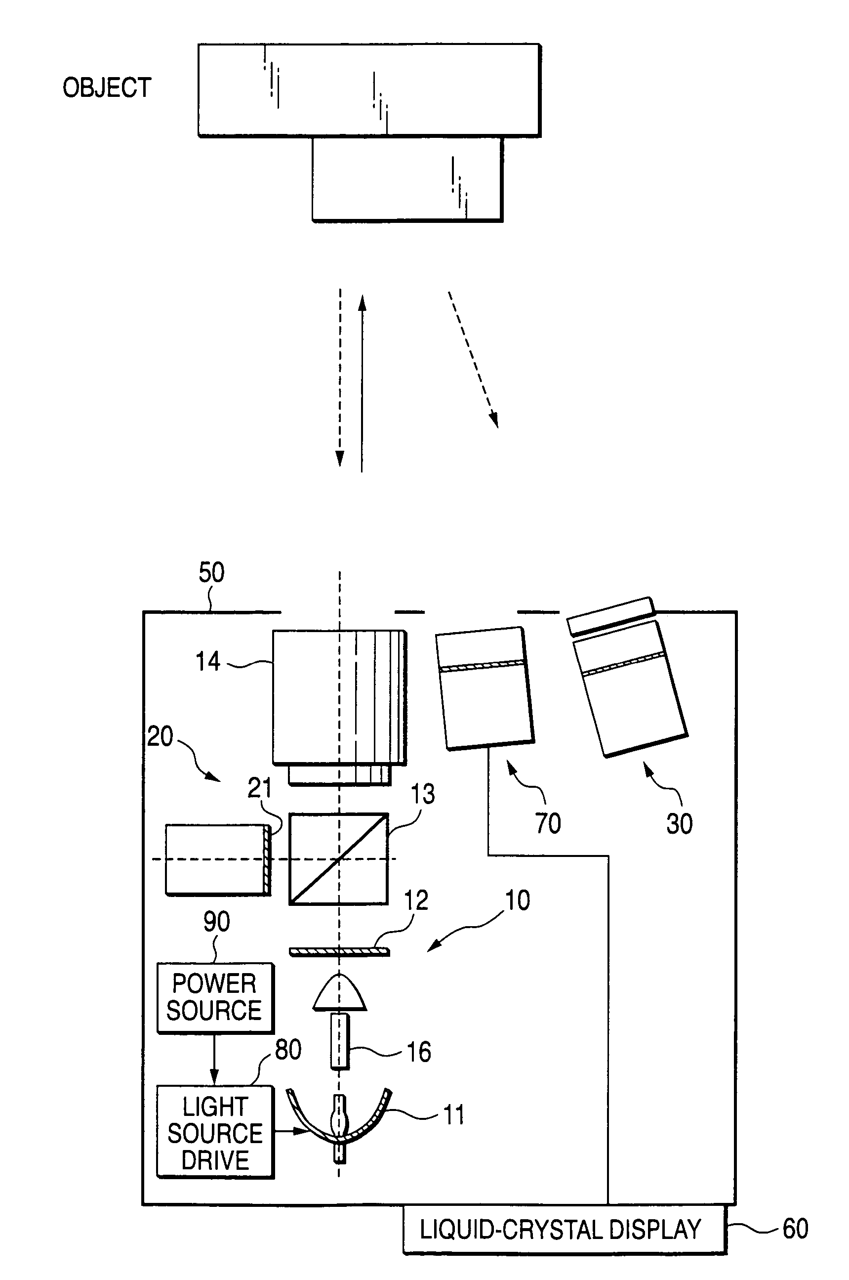
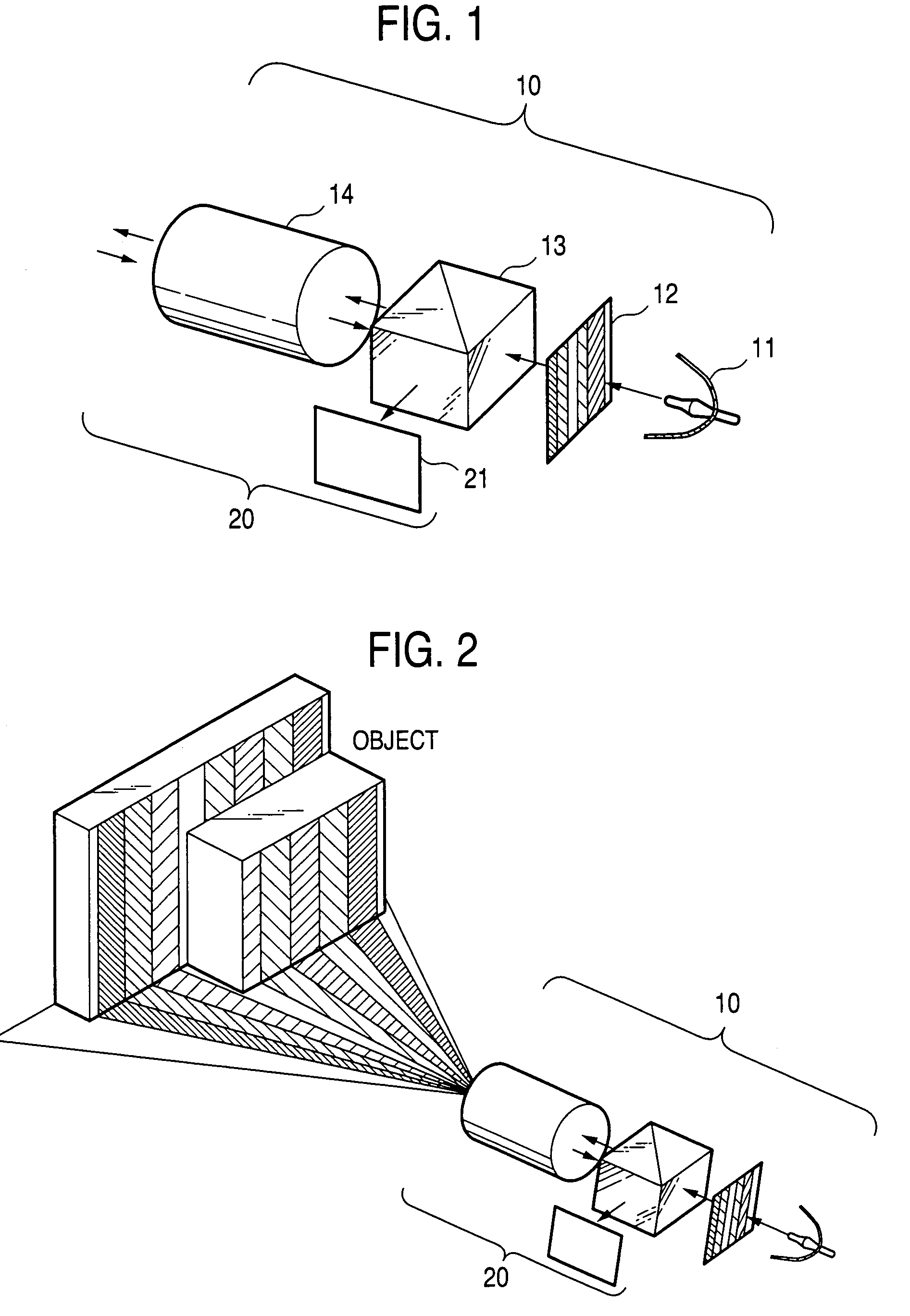
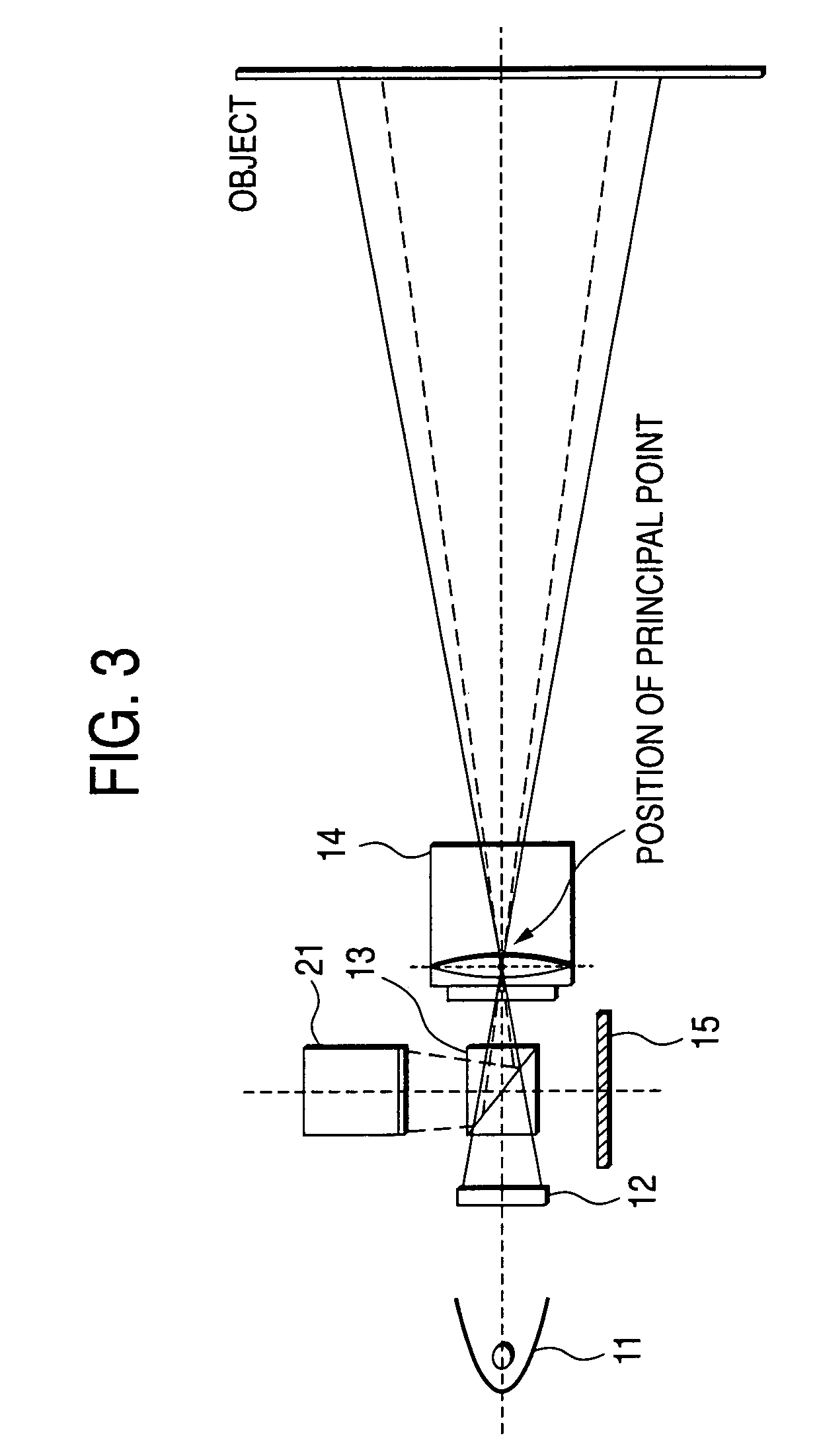
[0047]FIG. 1 schematically shows projector unit 10 which is the principal feature of a range finder of the invention; and first image capturing unit 20 located at a principal point optically identical with that of the projector unit 10. The schematic configuration of the entirety of the range finder of the present embodiment is shown in FIG. 4, and the configuration will be described later.

[0048]In FIG. 1, the projector unit 10 comprises a light source 11 for emitting light; a pattern generation section 12 for generating an encoded pattern; identical principal point arrangement unit 13 for placing the projector unit 10 at the principal point optically identical with that of first image capturing unit 20; and an image forming optical system 14 shared between the projector unit 10 and the first image capturing unit 20. A liquid-crystal panel or a transmitted film is used for the pattern generation section 12. If a liquid-crystal panel is used, the contrast or color of stripes constit...

sixth embodiment

[0089]A sixth embodiment will now be described. The previously-described Embodiments 1 through 5 have used a polarized beam splitter as the identical principal point arrangement unit and have utilized a polarization light converting function and a polarization light direction selection function, both belonging to the beam splitter. However, when the gloss of the object does not present any significant problem or when means for solving a problem related to a gloss is additionally adopted, the polarization light converting function and the polarization light direction selection function can be omitted. Subsequent embodiments employ identical principal point arrangement unit which does not have any polarization light converting function or polarization light direction selection function.

embodiment 6

[0090]FIG. 14 shows a range finder of In the drawing, elements which correspond to those shown in FIG. 4 are assigned corresponding reference numerals. The present embodiment employs a beam splitter (of cube or plate type) as identical principal point arrangement unit 13A. Second image capturing unit 30A has the texture pattern image capturing section 31 and the imaging optical system 32. However, the image capturing unit 30A is not provided with the polarizing direction selection unit (indicated by reference numeral 33 in FIG. 4).

[0091]Even in the range finder of Embodiment 6, the stripe images captured by the first image capturing unit 20 and the second image capturing unit 30A include texture data pertaining to the object. Hence, when corresponding points are extracted through comparison between the stripe images, occurrence of an error can be inhibited. Therefore, the influence of measurement deterioration attributable to the texture of the object can be lessened.

[0092]When the...


PUM


Abstract

A range finder for measuring a three-dimensional geometry of an object includes a projector unit for projecting the pattern light onto the object, a first image capturing unit for capturing an image reflected from the object, a second image capturing unit for capturing an image reflected from the object, an identical principal point arrangement unit, and an imaging optical system. Preferably, the second image capturing unit is arranged so as to assume a principal point optically differing from that of the first image capturing unit, the identical principal point arrangement unit arranges the projector unit and the first image capturing unit at the position of an optically identical principal point, and the imaging optical system is shared between the projector unit and the first image capturing unit.

Description

BACKGROUND OF THE INVENTION[0001]1. Field of the Invention[0002]The present invention relates to a three-dimensional image capturing technique optimal for collectively acquiring range data as well as intensity data by means of a triangulation method and through use of a plurality of cameras, and more particularly, to an attempt to realize a reduction in measurement errors, improved usability, and a compact range finder.[0003]2. Background Art[0004]Techniques for measuring the geometry of an object are roughly classified into passive techniques (i.e., triangulation and shape-from-X) and active techniques (time of flight and triangulation). A difference between the passive techniques and the active techniques lies in whether or not any energy is radiated onto an object. Generally, the active techniques can be said to be more resistant to noise than the passive techniques, because ambiguity in measurement can be eliminated. The triangular technique, which belongs to both categories of ...

Claims


Application Information

Patent Timeline
Patent Type & Authority Patents(United States)
IPC IPC(8): G01V8/00G01B11/25G01S7/499G01S17/89G06T1/00H04N5/225
CPCG01B11/2509G01B11/2545G01S7/499G01S17/89
Inventor YAMAGUCHI, YOSHINORI
Owner FUJIFILM BUSINESS INNOVATION CORP
Learn More