
Passive magnetic bearing for a motor-generator

a magnetic bearing and motor-generator technology, applied in the field of magnetic bearings, can solve the problems of poor adaptability of mechanical bearings, mechanical bearings, air bearings, etc., to use in vacuum, reduce unit efficiency, and friction loss

Inactive Publication Date: 2006-07-18
LAWRENCE LIVERMORE NAT SECURITY LLC
View PDF24 Cites 14 Cited by
  • Summary
  • Abstract
  • Description
  • Claims
  • Application Information

AI Technical Summary

Benefits of technology

[0011]Conductive lap windings are interleaved with conventional loops in the stator of a motor-generator. The rotor provides magnetic induction lines that, when rotated, cut across the lap windings and the loops. When the rotor is laterally displaced from its equilibrium axis of rotation, its magnetic lines of induction induce a current in the interleaved lap windings. The induced current interacts with the magnetic lines of induction of the rotor in accordance with Lenz's law to generate a radial force that returns the rotor to its equilibrium axis of rotation.

Problems solved by technology

This reduces the efficiency of the unit, and the designer must also contend with the attendant problems of heat and wear.
Even non-contact bearings, such as air bearings, involve frictional losses that can be appreciable and, in addition, are sensitive to dust particles.
Furthermore, mechanical bearings, and especially air bearings, are poorly adapted for use in a vacuum.

Method used


Image

  • Passive magnetic bearing for a motor-generator
  • Passive magnetic bearing for a motor-generator
  • Passive magnetic bearing for a motor-generator

Examples


Embodiment Construction

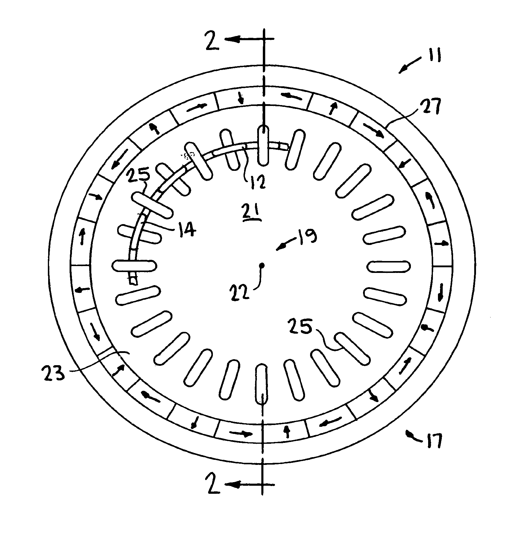
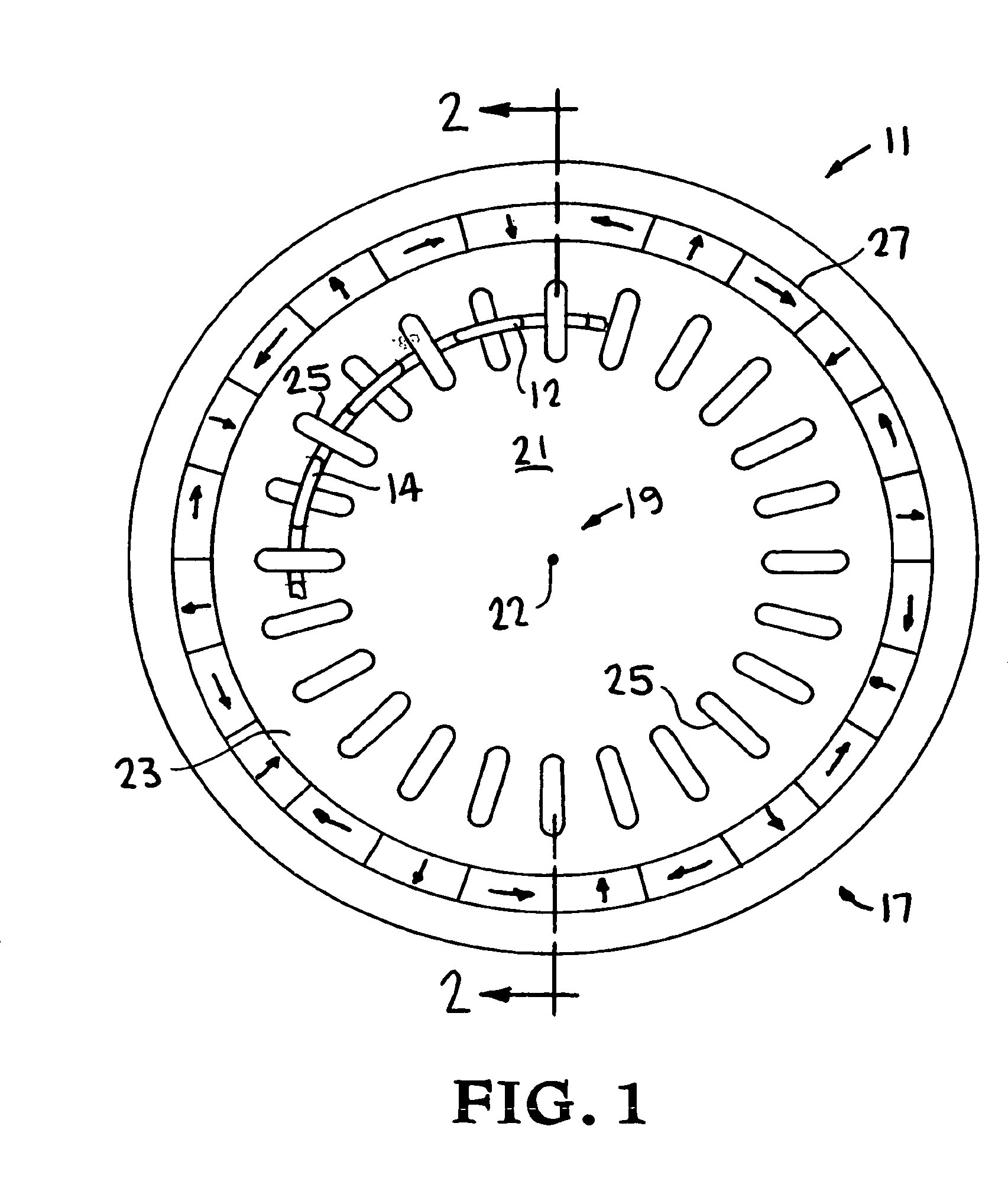
[0019]Turning to the drawings, FIG. 1 is a section front view of motor-generator 11 including conductive lap windings 12, 13, 14 and 15 of the present invention. Motor-generator 11 also includes rotor 17 rotating its longitudinal axis of symmetry 19 and around stator 21. As shown in FIG. 1, when rotor 17 is in equilibrium, axis 19 is collinear with longitudinal axis of symmetry 22 of stator 21. Radial gap 23 separates rotor 17 and stator 21. Gap 23 is uniform and cylindrical when rotor 17 is in its equilibrium position, and becomes asymmetrical when rotor 17 is displaced therefrom.

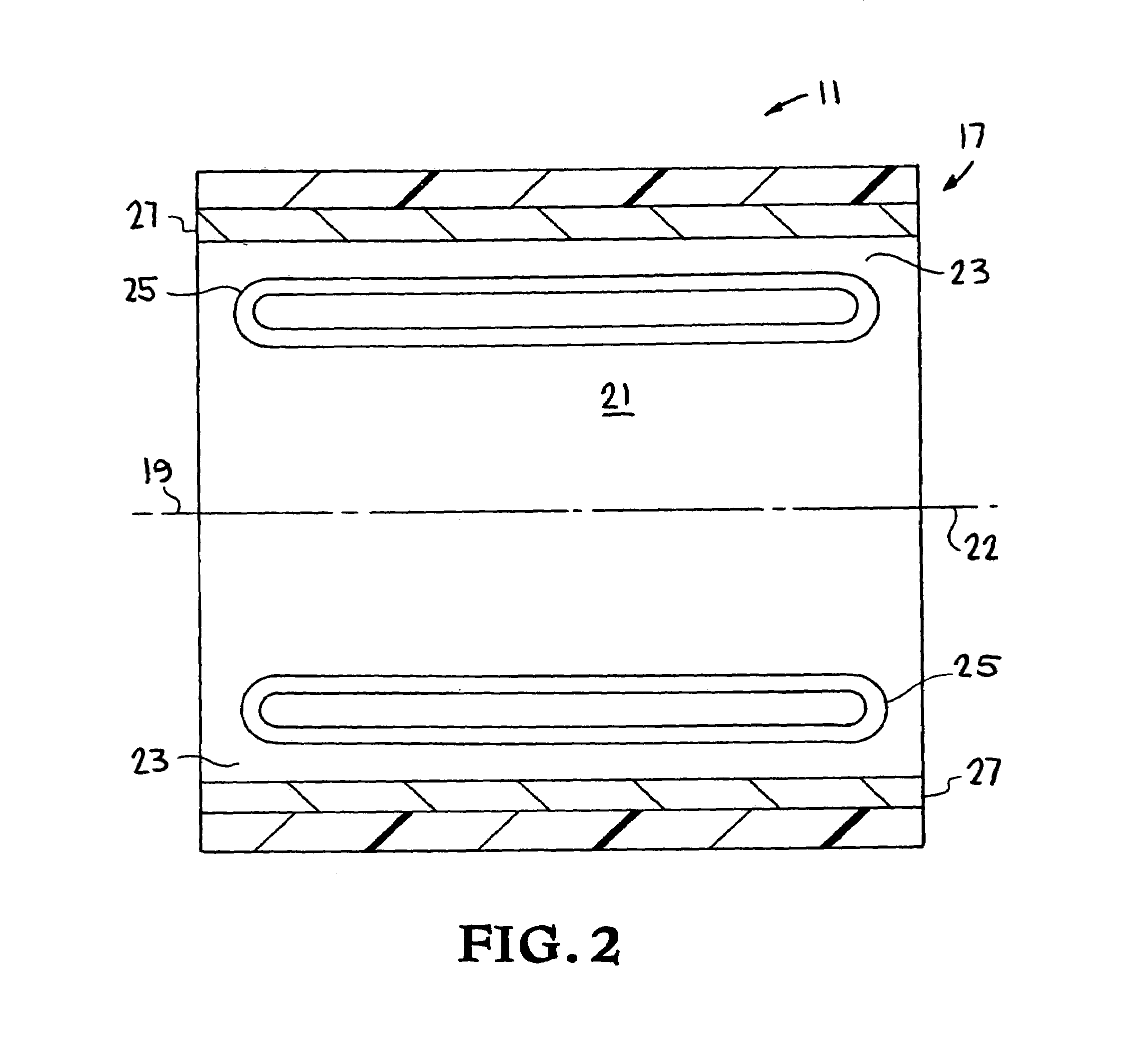
[0020]As also shown in FIG. 2, a section view taken along line 2—2 of FIG. 1, stator 21 includes conductive rectangular loops 25. Rotor 17 includes annular Halbach magnet array 27 that generates a magnetic field radially inward towards axis 19, having lines of induction that intersect lap windings 12, 13, 14 and 15, and loops 25. A discussion of Halbach magnet arrays is provided in K. Halbach, “Application...


PUM


Abstract

Conductive lap windings are interleaved with conventional loops in the stator of a motor-generator. The rotor provides magnetic induction lines that, when rotated, cut across the lap windings and the loops. When the rotor is laterally displaced from its equilibrium axis of rotation, its magnetic lines of induction induce a current in the interleaved lap windings. The induced current interacts with the magnetic lines of induction of the rotor in accordance with Lenz's law to generate a radial force that returns the rotor to its equilibrium axis of rotation.

Description

[0001]The United States Government has rights in this invention pursuant to Contract No. W-7405-ENG-48 between the United States Department of Energy and the University of California for the operation of Lawrence Livermore National Laboratory.BACKGROUND OF THE INVENTION[0002]1. Field of the Invention[0003]The present invention relates to magnetic bearings and, more particularly, to a passive magnetic bearing used to support and stabilize the rotor of a motor-generator.[0004]2. Description of Related Art[0005]An armature and a field winding comprise the primary elements of motors, generators and alternators. In low power applications, the armature rotates through the magnetic lines of induction provided by the stationary field winding. In this configuration, the armature composes the rotor part of the assembly, while the field winding is the stator. This is the design used in automobile alternators because the stator is on the outside of the rotor, and thus can be incorporated into a...

Claims


Application Information

Patent Timeline
Patent Type & Authority Patents(United States)
IPC IPC(8): H02K5/16H02K1/00H02K3/00H02K7/09F16C39/06
CPCH02K7/09F16C32/0436F16C2380/26
Inventor POST, RICHARD F.
Owner LAWRENCE LIVERMORE NAT SECURITY LLC
Learn More