Method of detecting phase difference, phase detector for performing the same and clock-and-data recovering device including the phase detector

a phase difference and phase detector technology, applied in the direction of voltage-current phase angle, pulse automatic control, instruments, etc., can solve the problem of deterioration of the jitter characteristic measured in the clock and data recovery (cdr) device using the phase detector

Inactive Publication Date: 2006-07-18
SAMSUNG ELECTRONICS CO LTD
View PDF4 Cites 14 Cited by
  • Summary
  • Abstract
  • Description
  • Claims
  • Application Information

AI Technical Summary

Benefits of technology

[0007]In an exemplary embodiment, the present invention provides a phase detector that detects the phase difference between input signals at the same or substantially the same speed as that of the conventional phase detector and the jitter measured in a clock and data recovery (CDR) device using the phase detector according to exemplary embodiments of the present invention is reduced, or that detects the phase difference between input signals at high-speed without substantially deteriorating the jitter measured in the CDR device using the phase detector according to exemplary embodiments of the present invention.
[0020]According to exemplary embodiments of the present invention, the phase detector lowers the level of the phase difference signal having a phase difference lower than 45°, and thus the operational speed of the CDR device may be maintained to have the same level of that of the CDR device using the conventional phase detector and the jitter characteristics may be enhanced.
[0021]In addition, the phase detector maintains the level of the phase difference signal having a phase difference lower than 45° as a low level and maintains the level of the phase difference signal having a phase difference higher than 45° as a high level, and thus the operational speed of the CDR device may be enhanced and the jitter characteristics may not be deteriorated compared with the CDR device using the conventional phase detector.

Problems solved by technology

Therefore, when the conventional bang-bang phase detector is used in a clock and data recovery (CDR) circuit, the conventional bang-bang phase detector outputs a phase difference signal having unnecessarily a high voltage level when the phase difference signal has a phase difference lower than 45°, and a pull-in time (or lock time) in a charge pump of the clock and data recovery (CDR) increases, and a jitter characteristic measured in the clock and data recovery (CDR) device using the phase detector may be deteriorated.

Method used


Image

  • Method of detecting phase difference, phase detector for performing the same and clock-and-data recovering device including the phase detector
  • Method of detecting phase difference, phase detector for performing the same and clock-and-data recovering device including the phase detector
  • Method of detecting phase difference, phase detector for performing the same and clock-and-data recovering device including the phase detector

Examples


Embodiment Construction

[0043]Hereinafter the exemplary embodiments of the present invention will be described in detail with reference to the accompanying drawings.

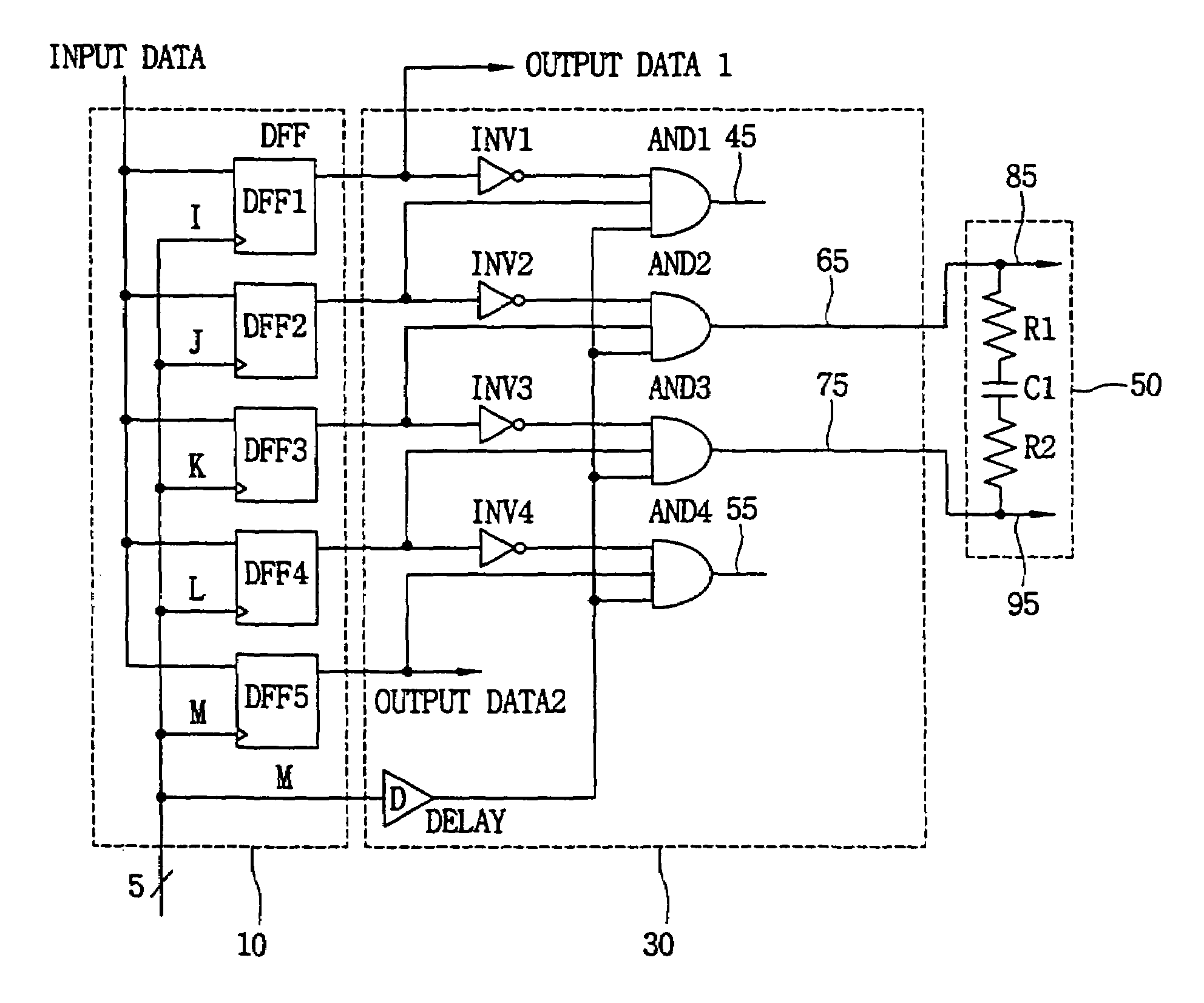
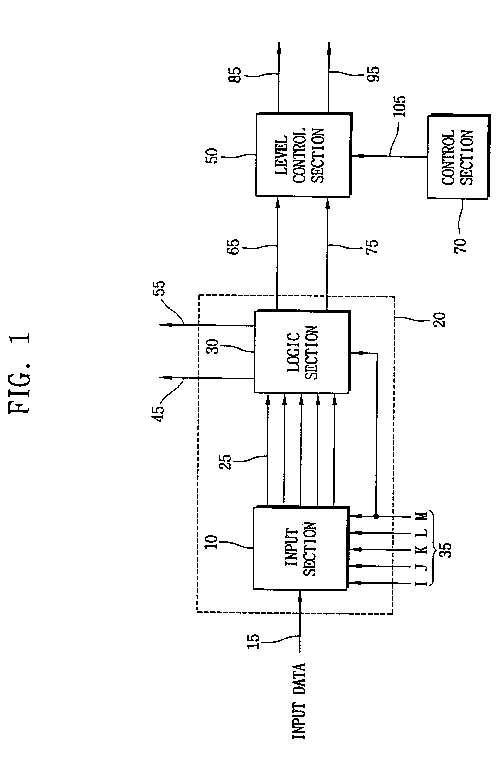
[0044]FIG. 1 is a block diagram showing a phase detector according to an exemplary embodiment of the present invention.

[0045]Referring to FIG. 1, the phase detector according to an exemplary embodiment of the present invention includes a phase difference signal generating section 20 and a level control section 50. A phase difference signal generating section according to another exemplary embodiment of the present invention may further include a control section 70.

[0046]The phase difference signal generating section 20 includes an input section 10 and a logic section 30. In an exemplary embodiment, the phase detector may be a bang-bang phase detector.

[0047]The phase difference signal generating section 20 generates a first phase difference signal 45 having a first phase difference, a fourth phase difference signal 55 having a fourth phase diffe...


PUM


Abstract

First and fourth phase difference signals, and first and second phase difference information signals respectively having first, fourth, second and third phase differences may be generated using an input signal and a plurality of clock signals each of which has different phase with each other. A level of the first phase difference information signal may be lowered, and a second phase difference signal having a first level less than levels of the first and fourth phase difference signals may be generated. A level of the second phase difference information signal may be lowered, and a third phase difference signal having a second level less than the levels of the first and fourth phase difference signals may be generated. The level of the phase difference signals having a phase difference lower than 45° may be lowered, and thus the operational speed of a CDR device may be maintained and / or the jitter characteristics may be enhanced.

Description

CROSS-REFERENCE TO RELATED APPLICATIONS[0001]This application claims priority upon Korean Patent Application No. 2003-51716 filed on Jul. 26, 2003, the contents of which are herein incorporated by reference in its entirety.BACKGROUND OF THE INVENTION[0002]1. Field of the Invention[0003]The present invention relates to a method of detecting a phase difference, a phase detector for performing the same and a clock and data recovering (CDR) device including the phase detector. More particularly, the present invention relates to a method of detecting a phase difference for reducing jitter while maintaining the operation speed, a phase detector for performing the same and a clock and data recovering device including the phase detector.[0004]2. Description of the Related Art[0005]A bang-bang phase detector is a conventional phase detector for high-speed interface applications. A conventional bang-bang phase detector detects a phase difference between input signals and outputs a phase diffe...

Claims


Application Information

Patent Timeline
Patent Type & Authority Patents(United States)
IPC IPC(8): G01R29/00H03L7/085H03D13/00
CPCH03D13/003H03L7/085
Inventor KIM, NYUN-TAE
Owner SAMSUNG ELECTRONICS CO LTD
Why Eureka
Try Eureka